
User Manual
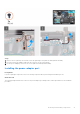
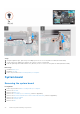
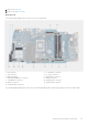
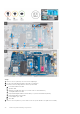

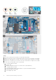
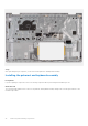
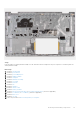
Table Of Contents
- Vostro 3525 Service Manual
- Contents
- Working inside your computer
- Removing and installing components
- Recommended tools
- Screw list
- Major components of Vostro 3525
- Secure Digital (SD) Card
- Base cover
- Battery
- Memory modules
- M.2 solid-state drive
- Wireless card
- Fan
- Speakers
- Hard drive assembly
- I/O board
- I/O daughter board FFC
- Heat sink
- Power-button board
- Power button with fingerprint reader
- Display assembly
- Display bezel
- Display panel
- Hinge caps
- Hinges
- Camera module
- eDP cable
- Display cover and antenna assembly
- Touchpad
- Power-adapter port
- System board
- Palm-rest and keyboard assembly
- Drivers and downloads
- BIOS setup
- Troubleshooting
- Handling swollen Lithium-ion batteries
- Dell SupportAssist Pre-boot System Performance Check diagnostics
- Built-in self-test (BIST)
- System-diagnostic lights
- Recovering the operating system
- Real-Time Clock (RTC Reset)
- Backup media and recovery options
- WiFi power cycle
- Drain residual flea power (perform hard reset)
- Getting help and contacting Dell

5. Remove the single (M2x2) screw that secures the system board to the palm-rest assembly.
6.
NOTE: For systems shipped with a USB Type-C port, do not remove the type-C bracket that is secured to the system
board.
7. Carefully lift the system board away from the chassis.
Installing the system board
Prerequisites
If you are replacing a component, remove the existing component before performing the installation process.
About this task
The following image indicates the connectors on your system board.
1. Fan connector 2. I/O board FFC connector
3. eDP connector 4. DC-in port connector
5. Memory modules 6. Keyboard FFC connector
7. Keyboard-backlight FFC connector 8. Battery connector
9. Touchpad FFC connector 10. Hard drive FFC connector
11. Wireless connector 12. Speaker cable connector
13. Solid-state drive connector
The following images indicate the location of the system board and provide a visual representation of the installation procedure.
Removing and installing components
95