CX300 2-Gigabit Fibre Channel Disk Processor Enclosure (DPE2) SETUP GUIDE P/N 300-001-276 REV A05 EMC Corporation Corporate Headquarters: Hopkinton, MA 01748-9103 1-508-435-1000 www.EMC.
Notice Copyright © 2004-2005 EMC Corporation. All rights reserved. Printed August, 2005 EMC believes the information in this publication is accurate as of its publication date. However, the information is subject to change without notice. THE INFORMATION IN THIS PUBLICATION IS PROVIDED “AS IS.
Overview This guide explains how to install and initialize an EMC® CLARiiON® CX300 2-gigabit disk processor enclosure (DPE2). Only an authorized service provider should install and cable hardware. Customers can perform all the other procedures in this guide or have an authorized service provider do them.
Step 1 Plan Your Configuration To plan your installation, refer to the EMC CLARiiON CX300, CX300i, CX500, CX500i, and CX700 Storage Systems Configuration and Planning Guide (on the EMC Powerlink website or the documentation CD). The guide includes background material, planning rules, and administrative worksheets. Use it to choose and understand RAID types, LUNs, file systems, and software options.
Step 2 Prepare Your Environment 1. Verify that your facility has adequate network wiring to provide each storage-system storage processor (SP) with a management port Ethernet connection. 2. Confirm that your facility has appropriate electrical wiring in place to accommodate your cabinet’s power cords. For EMC cabinets, see the Site Preparation and Unpacking Guide for the 40U-C Cabinet (on the EMC Powerlink website or the documentation CD).
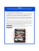
Step 3 Verify the Parts Verify that your basic configuration has the following parts: ❒ CX300 DPE2with: ❒ Two storage processors (SPs) ❒ Two power supply/system cooling (power/cooling) modules ❒ Minimum of five disk drives ❒ At least one standby power supply (SPS) for systems that will use ac power Power/Cooling Module B Disk Drives Power/Cooling Module A SP B Front View (Bezel Removed) SPS Tray SP A Back View SPS B SPS A EMC2791 ❒ Optional 2-gigabit disk-array enclosures (DAE2s or DAE2Ps) ❒ 1-mete
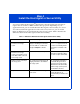
Step 4 Install the Host Agent or Server Utility You can use either the Navisphere® Host Agent or the Navisphere Server Utility to register the server NICs or HBAs with the storage system. Depending on your application needs, you can install either the Host Agent or Server Utility on a server. You cannot install both applications on the same server; however, you can install them on different servers attached to the same storage system.
Step 4 Continued Install the Host Agent or Server Utility If you have not already installed the Host Agent or the Server Utility, install it now. Follow the instructions in the installation guide listed below for the operating system running on each server connected to the storage system. These installation guides are on the EMC Powerlink website and the documentation CD.
Step 5 Install the Storage System in the Cabinet If your CX300 DPE2 enclosure or any DAEs are not already installed in a cabinet, install them using the instructions for installing 3U devices in the EMC Rails and Enclosures Field Installation Guide. IMPORTANT The disk modules in slots 0 through 4 of the DPE2 (enclosure 0, loop 0) provide mirrored boot and recovery capability, and are preconfigured according to their slot assignment before shipment.
Step 6 Verify Storage System Back-End Connections Use the information below and the diagram to verify the enclosure address settings and loop (bus) cabling for the DPE2 and any DAEs. The CX300 DPE2 supports a single redundant Fibre Channel back-end loop (0). The two independent loops from SP A and SP B are paired, and share access to the same dual-port disk drives. Without an additional DAE, the CX300 DPE2 has its single redundant loop over the midplane, and does not require back-end cabling.
Step 7 Verify Power Settings and Connections 1. Verify that the cabinet master switches are in the off position. 2. For systems that use ac power, verify that the power switch on each SPS is off. 3. Verify that the power switch on each DPE2 and any DAE power/cooling module is off (if present). 4. For high availability, verify that A and B power/cooling modules in each enclosure are connected to different power strips. 5. Verify that all power connections are correct and fully seated.
Step 7 Continued Verify Power Settings and Connections • In systems with dc power, connect DB9-RJ12 sense cables (sometimes called SPS emulator cables) between each power supply and the SPS serial connector on its corresponding storage processor, as shown below. SP B SP A +- EMC2960 • dc power cords from power/cooling module A (PS A) and PS B connect directly to independent sources of dc power. 6. Connect the cabinet ac/dc power cords to the power outlets in your facility.
Step 8 Start the Storage System 1. Turn on the power switches for the DPE2 and any DAE power/cooling modules (if present). 2. Turn on the power switch for each SPS. 3. Be sure any other devices in the cabinet are correctly installed and ready for powerup, then a. Plug the power cords into the power outlets in your facility. (Standard EMC cabinets use two 240-volt ac cables.) Connect each power cable to a different branch circuit. Both power cords must be connected to the appropriate power supply. b.
Step 9 Connect the Storage System Management Ports Using CAT 5 or better Ethernet cables, connect each SP to the same subnet that is connected to the host from which you will manage the storage system (management host).
Step 10 Initialize the Storage System To initialize the storage system, you must configure the management network interfaces for the storage system’s storage processors (SPs) with the Navisphere Storage System Initialization Utility. Requirements for Initialization Make sure you have the following: ❒ FLARE™ Operating Environment (OE) software version 2.16.300.5.yyy.1 or higher installed on the storage system. A card that ships with the storage system tells you the FLARE version that is installed.
Step 10 Continued Initialize the Storage System ❒ The completed configuration planning worksheets from the EMC CLARiiON CX300, CX300i, CX500, CX500i, and CX700 Storage Systems Configuration Planning Guide (on the EMC Powerlink website or the documentation CD) with the following information: ❒ A static IP address for each storage processor in the storage system. ❒ The subnet mask of the LAN to which each storage-system management port and host is connected.
Step 10 Continued Initialize the Storage System Install the Navisphere Storage System Initialization Utility Install the Storage System Initialization Utility on a host that is connected to the same subnet as the storage system following the instructions in the installation guide listed below for the operating system running on the host. These installation guides are on the EMC Powerlink website and the documentation CD.
Step 10 Continued Initialize the Storage System 2.
Step 10 Continued Initialize the Storage System 4. Select the storage system to initialize: • On an HP-UX, Linux, NetWare, or Solaris host Enter the item number for the storage-system’s serial number and press Enter. • On a NetWare Client or Windows host In the Uninitialized Systems list select the storage-system’s serial number and click Next. 5. Enter the name you want for the storage system, which cannot exceed 32 characters. 6.
Step 11 Connect the Storage-System Data Ports You use fiber-optic cables to connect the storage-system data ports to the server’s Fibre Channel HBAs or to ports on a Fibre Channel switch that is connected to the server. 1. Remove the protective covers from each optical connector on the fiber-optic cable and on the HBA or switch port. 2. Plug the cables into the Fibre Channel front-end ports (FE 0 and FE 1) on the SPs. 3. Connect the free end of each fiber-optic cable: a.
Step 11 Continued Connect the Storage-System Data Ports What Next? If you installed the Host Agent on the server, continue to Step 12, Run the Host Agent to Register the Server HBAs on page 20. If you installed the Server Utility on the server, go to Step 13, Run the Server Utility to Register the Server HBAs on page 22.
Step 12 Run the Host Agent to Register the Server HBAs When the Host Agent starts, it registers server HBAs with any storage systems that are connected to the HBAs either directly or through switches. It does this registration by sending the HBA initiator records to the storage systems. For certain operating systems, the Host Agent starts automatically when you boot the server.
Step 12 Continued Run the Host Agent to Register the Server HBAs • NetWare server To start the Host Agent: load sys:\emc\agent\navagent -f sys:\emc\agent\agent.cfg To stop the Host Agent: unload navagent • Solaris server To start the Host Agent: /etc/init.d/agent start To stop the Host Agent: /etc/init.d/agent stop • Windows Server 2003 or Windows 2000 server To start the Host Agent: a.
Step 13 Run the Server Utility to Register the Server HBAs 1.
Step 14 Enable Software The following software is enabled on the storage system prior to shipment from the factory: • • Navisphere Manager Access Logix™ If you have any of the following optional software and it is not already enabled, you need to enable it: • • SnapView™ Analyzer Enable Optional Software Use the Software Installation Wizard of Navisphere Manager to install the enabler (.ena file) from the CD that shipped with the software kit.
Step 15 Configure the Storage System You are now ready to use Navisphere Manager to define your storage-system security settings and configure your storage system. Refer to the appropriate checklist for your system in the EMC Installation Roadmap for CX-Series, AX-Series, and FC-Series Storage Systems (P/N 069001166) on the EMC Powerlink website.
If You Need Help For questions about technical support and service, contact your service provider. If you have an EMC service contract, contact EMC Customer Service at USA (800) 782-4362, Canada (800) 543-4782, or worldwide (508) 497-7901. For questions about upgrades, contact your local sales office.