
Setup guide


9
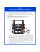
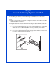
Step 7
Verify Power Settings and Connections
1. Verify that the cabinet master switches are in the off position.
2. For systems that use ac power, verify that the power switch on each SPS is off.
3. Verify that the power switch on each DPE2 and any DAE power/cooling module
is off (if present).
4. For high availability, verify that A and B power/cooling modules in each
enclosure are connected to different power strips.
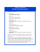
5. Verify that all power connections are correct and fully seated.
• In systems with ac source power, standby power supply A (SPS A) connects to
the SPS serial port (marked with a battery symbol) on SP A; if present, SPS B
connects to SP B.
• The ac line cord from power/cooling module (PS) A connects to the standby
power supply (SPS). If only one SPS is available, the PS B power cord connects
to the closest power strip. If a second SPS is available, the PS B power cord
connects to SPS B. Whenever possible, connect SPS A and PS B to independent
circuits. Do not connect PS A and PS B to the same SPS.
• If you have two SPSs, they connect to separate power distribution units
(PDUs) in the cabinet.
SP B
SP A
!!
!!
!
EXP PRI
EXPPRI
#
!
EXP PRI
EXPPRI
#
A
B
!!
!!
!
EXP PRI
EXPPRI
#
!
EXP PRI
EXPPRI
#
A
B
!!
!!
!
EXP PRI
EXPPRI
#
!
EXP PRI
EXPPRI
#
A
B
DAE
DAE
DAE
ON
I
OFF
O
ON
I
OFF
O
ON
I
OFF
O
ON
I
OFF
O
ON
I
OFF
O
ON
I
OFF
O
EMC3216
SPS A
240 V
Power/
Cooling
Module B
Power/
Cooling
Module A
Master
Switch
PDU
PDP
SPS
+
-