Dell™ PowerEdge Expandable RAID Controller 3/QC, 3/DC, 3/DCL and 3/SC WebBIOS Configuration Utility Guide www.dell.com | support.dell.
____________________ Information in this document is subject to change without notice. ©2002DellComputerCorporation.Allrightsreserved. Reproduction in any manner whatsoever without the written permission of Dell Computer Corporation is strictly forbidden. Trademarks used in this text: Dell, the DELL logo, Dell OpenManage and PowerEdge are trademarks of Dell Computer Corporation. MegaRAID is a registered trademark of LSI Logic Corporation.
Contents 1 WebBIOS Configuration Utility Features . . . . . . . . . . . . . . . . . . . . . . . . . . . . . . . Starting the WebBIOS Utility Main Menu Screen . . . . . . . . . . . . . . . . . . . . . . . 3 4 . . . . . . . . . . . . . . . . . . . . . . 5 . . . . . . . . . . . . . . . . . . . . . . . . . 7 . . . . . . . . . . . . . . . . . . . . . . . . . . . . 9 WebBIOS Toolbar Icons Adapter Properties Scan Devices SCSI Channel Properties Properties . . . . . . . . . . . . . . . . . . . . . . .
Configuration Mismatch . . . . . . . . . . . . . . . . . . . . . . 26 . . . . . . . . . . . . . . . . . . . . . . 27 . . . . . . . . . . . . . . . . . . . . . . . . . . . . 27 Random Array Deletion Overview Configuration Constraints . . . . . . . . . . . . . . . . . . . Procedure for Deleting Logical Drives Index 2 Contents 28 . . . . . . . . . . . . . 29 . . . . . . . . . . . . . . . . . . . . . . . . . . . . . . . . . . .
1 SECTION 1 WebBIOS Configuration Utility Features Starting the WebBIOS Utility WebBIOS Toolbar Icons Adapter Properties Scan Devices SCSI Channel Properties Logical Drives Physical Drives Configuration Wizard Adapter Selection Physical View\Logical View Configuration Mismatch Random Array Deletion
w w w . del l .c om | s upp ort .d el l. c om Features The WebBIOS Configuration Utility allows you to configure and manage RAID arrays and logical drives. WebBIOS is an HTML-based utility that is embedded in the firmware in the PERC 3 controller. NOTE: The term "PERC 3" in this document refers to PERC 3/QC, PERC 3/DC, PERC 3/DCL, and PERC 3/SC. NOTE: The BIOS Configuration Utility ( ) is also used to configure and maintain RAID arrays, and logical drives and to manage the RAID system.
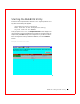
Starting the WebBIOS Utility When the host computer boots, hold the key and press the key when the following text appears: Copyright© LSI Logic Corporation Press to Run Configuration Utility Or press for WebBIOS After you press , the Adapter Selection screen displays. You use this screen to select the adapter that you want to configure. Select an adapter and press Start to begin the configuration.
w w w . del l .c om | s upp ort .d el l. c om NOTE: If there is a configuration mismatch between the disks and the NVRAM (Non-volatile Random Access Memory) on the adapter, the Select Configuration screen appears first. This screen is used to perform custom configuration, auto configuration with redundancy (recommended), or auto configuration without redundancy. See page 17 for information about selecting configurations, and page page 26 for information about configuration mismatches.
WebBIOS Toolbar Icons Table 1-1 describes the WebBIOS toolbar icons. Table 1-1. WebBIOS Toolbar Icons Icon Description Click this icon to return to the WebBIOS main menu screen ("home page"). Go to Home Page Click this icon to return to the page you accessed immediately before the current page. Go to Previous Page Click this icon to exit the WebBIOS utility. Exit WebBIOS Utility Click this icon to display the adapters that you can select.
w w w . del l .c om | s upp ort .d el l. c om T a b l e 1 - 1 . W e b B I O S T o o l b a r I c o n s (continued) Icon Description Click this icon to turn off the sound on the alarm. Silence the Alarm Click this icon to go from the WebBIOS Configuration Utility to the BIOS Configuration Utility that resides in the firmware. Go to BIOS Configuration Utility The BIOS Configuration Utility () is used to configure and maintain RAID arrays and logical drives and to manage the RAID system.
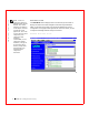
Adapter Properties The Adapter Properties screen appears when you select Adapter Properties from the WebBIOS Main Menu screen. WebBIOS Adapter Properties Screen Table 1-2 describes the Adapter Properties menu options. Table 1-2.
w w w . del l .c om | s upp ort .d el l. c om T a b l e 1 - 2 . A d a p t e r P r o p e r t i e s M e n u O p t i o n s (continued) Option Description Initiator ID Identifying number for the card. You can change the Initiator ID only when you are in cluster mode. You cannot change the ID while in standard mode. The ID can be a number from 0 to 15. We recommend that you use 6 or 7. When you are in standard mode, the ID is always 7.
T a b l e 1 - 2 . A d a p t e r P r o p e r t i e s M e n u O p t i o n s (continued) Option Description Fast Initialization When enabled, zeros are written to the first sector of the logical drive so that initialization occurs in 2 – 3 seconds. When disabled, a full initialization takes place on the entire logical drive. On a larger array (over 5 arrays), it is best to set fast initialization to Disabled, then initialize.
w w w . del l .c om | s upp ort .d el l. c om SCSI Channel Properties The SCSI Channel Properties screen displays when you select SCSI Channel Properties from the WebBIOS Main Menu screen: WebBIOS SCSI Channel Properties Screen Properties The properties under the Properties heading are Channel Width, Termination, and SCSI Capabilities. The Channel Width row displays the SCSI bus width, in bits. You can change the options for the options Termination, and SCSI Capabilities.
SCSI Channels The SCSI Channels section of the screen lists the channels on the selected controller, and the values for the properties. Click Submit to save changes to the options. Click Reset to undo any changes and return to the configuration that existed before you made any changes. Other Options The other options on this screen are: • Home: Click Home to return to the main menu screen. • Back: Click Back to return to the previous screen.
w w w . del l .c om | s upp ort .d el l. c om Logical Drives The Logical Drives screen displays when you select Logical Drives from the Main Menu screen or click a logical drive in the list of logical drives on the Main Menu screen. WebBIOS Logical Drives Screen The upper right section of the screen displays the logical drives that currently exist. Below that section are options to: • Initialize a logical drive CAUTION: Initializing a logical drive destroys all data on the logical drive.
Initialize You should use the Initialize option to initialize each new logical drive that you configure. Perform the following steps to initialize a logical drive: 1 Select the Logical Drives option from the WebBIOS Main Menu screen. 2 On the Logical Drive Definition screen, select the logical drive to be initialized. 3 Select Initialize below the list of drives and click Go. The progress of the initialization appears as a graph on the screen.
w w w . del l .c om | s upp ort .d el l. c om The Check Consistency screen shows a check in progress. Check Consistency Screen Properties Select this option to perform the following: 14 • Display the logical drive properties. • Display or change the read, write, and I/O policies. • Enable or disable virtual sizing. (Virtual sizing allows PERC to determine the drive capacity. Set this option to Enabled before you add a physical drive to a logical drive.
• Allow RAID migration. RAID migration means changing the RAID level of the array. You can optionally add one or more drives to the array when you change the RAID level. The following is an example of the Properties screen. WebBIOS Properties Screen Boot from a Logical Drive After you select a logical drive to boot from, the system boots from that logical drive when you reboot. This field is 0-n, where n = the number of logical drives created on the controller – 1.
w w w . del l .c om | s upp ort .d el l. c om Physical Drives The Physical Drives screen displays when you select Physical Drives from the Main Menu screen or click a physical drive in the list of physical drives on the Main Menu screen. WebBIOS Physical Drives Screen NOTE: Only two channels display for PERC 3/DC, and PERC 3/DCL controllers, and one for PERC 3/SC controllers. 16 This screen displays the physical drives for each channel.
Configuration Wizard The Configuration Wizard screen displays when you select Configuration Wizard on the WebBIOS Main Menu screen. Configuration Wizard Screen On this screen, you can begin the procedure to clear a configuration, create a new configuration, or add a configuration. After you select one of the options, click Next to go to step 2/5.
w w w . del l .c om | s upp ort .d el l. c om Select Configuration Step 2/5 displays on the Select Configuration screen. On this screen, you can select custom configuration, auto configuration with redundancy, or auto configuration without redundancy. Select Configuration Screen Click Next to go to Step 3/5 after you select the type of configuration.
Array Definition The Array Definition screen displays next. To add drives to an array, press and hold the Ctrl key while you select "ready" drives on the left side of the screen. Click Accept Array to add the drives. To undo the changes, press Reclaim. Click Next to go to Step 4/5. The Array Definition screen shows an example of an array being added.
w w w . del l .c om | s upp ort .d el l. c om Logical Drive Definition The Logical Drive Definition screen displays for Step 4/5. Click a logical drive to display the following screen for that drive. Use this screen to configure the logical drive: Logical Drive Definition Screen Perform the following steps to configure logical drive policies. NOTE: Only applicable RAID levels can be chosen. For example, if there are two drives, you cannot select RAID 5, which requires a minimum of three drives.
A larger stripe size produces higher read performance, especially if your computer does mostly sequential reads. However, if your computer does random read requests more often, choose a smaller stripe size. Select the stripe size based on your performance testing. 4 Select the Read Policy. The Read Policy controls the SCSI read-ahead feature for the logical drive. During a read operation, the read-ahead policy determines whether the controller reads additional data records into cache.
w w w . del l .c om | s upp ort .d el l. c om 6 Select the Cache Policy. The Cache Policy determines whether reads for a specific logical driver use cache memory. It does not affect the Read-ahead cache. The options are as follows: 7 – Cached I/O: All reads are buffered in cache memory. – Direct I/O (default): Reads are not buffered in cache memory. Direct I/O does not override the cache policy settings. Data is transferred to cache and the host concurrently.
Configuration Preview Step 5/5 displays a preview of the configuration that you have create in the shown in Configuration Preview screen. Click Accept to save the configuration or Back to return to the previous screens and change the configuration.
w w w . del l .c om | s upp ort .d el l. c om Adapter Selection When you select Adapter Selection on the WebBIOS Main Menu screen, the Adapter Selection screen displays a list of the Dell PERC 3 adapters in the system. (This screen also appears when you first start the WebBIOS utility.) To begin configuration, select an adapter and click Start.
Physical View\Logical View The Physical View and Logical View display on the WebBIOS Main Menu screen. The option toggles between the Physical View and the Logical View of the logical drive. For example, if you select Physical View on the screen below, the option changes to Logical View. If you then click Logical View, the option changes back to Physical View. This allows you to go back and forth between physical and logical views.
w w w . del l .c om | s upp ort .d el l. c om Configuration Mismatch A configuration mismatch occurs when the data in the non-volatile random access memory (NVRAM), and the hard drives are different. The Configuration Mismatch screen provides three ways to resolve a configuration mismatch: • Select Create New Configuration to delete the previous configuration and create a new configuration. • Select View Disk Configuration to restore the configuration from the hard disk.
Random Array Deletion The PERC controllers support random array deletion. Random array deletion is the ability to delete any unwanted logical drives and use that space for a new logical drive. Overview The main benefit is that you are no longer restricted to sequential or contiguous logical drives when you create logical drives. You can use WebBIOS to create the next logical drive from the non-contiguous free space (‘holes’), and from the newly created arrays.
w w w . del l .c om | s upp ort .d el l. c om NOTE: When a ‘delete’ request reaches the operating system driver, the driver stops all the running input/output (I/O) for other logical drives and processes the delete request first. Normal read/write operation resumes after the delete request is completed. NOTE: The available space is shown on the Array Definition screen, on page 19.
Procedure for Deleting Logical Drives To delete logical drives in WebBIOS, perform the the following steps: 1 On the Main Menu screen, click Logical Drives. The Logical Drive screen displays. 2 On the Logical Drive screen, click Properties, then click Go. 3 The Properties screen displays. 4 Select a logical drive. 5 In the Operations section of the screen, select Delete and click Go. This deletes the logical drive.
30 WebBIOS Configuration Utility w w w . del l .c om | s upp ort .d el l.
Index A F P Adapter Properties, 7 FlexRAID PowerFail, 8 PERC, 14, 29 Adapter Selection, 24 Formatting, 27 Physical Drives, 16 Physical ViewView, 25-2 6 Adaptive, 21 Alarm Control, 8 Array Definition, 19 Auto Rebuild, 9 I Icons, 5 Initialization Logical Drives, 29 BIOS, 2 9 L BIOS Configuration Utility, 29 Logical Drive Definition, 20 Cache Policy, 22 Cached I/O, 22 R RAID, 2, 6 B C Policy Cache, 22 Logical Drives, 12 Check Consistency, 13 Initializing, 13 Properties, 14 Read-ahead, 21
32 Index W Web BIOS Configuration Utility, 1 WebBIOS Icons, 5 Write Policy, 21 Write-back, 21 Write-through, 21 32 Index
Printed in the U.S.A. P/N 48TCJ Rev. A04 www.dell.com | support.dell.