Dell™ OpenManage™ Server Administrator Version 5.2 CIM Reference Guide w w w. d e l l . c o m | s u p p o r t . d e l l .
Notes and Notices NOTE: A NOTE indicates important information that helps you make better use of your computer. NOTICE: A NOTICE indicates either potential damage to hardware or loss of data and tells you how to avoid the problem. COMMENT ____________________ Information in this document is subject to change without notice. © 2003–2007 Dell Inc. All rights reserved. Reproduction in any manner whatsoever without the written permission of Dell Inc. is strictly forbidden.
Contents 1 Introduction . . . . . . . . . . . . . . . . . . . . . . . . . . . . . . . . . Server Administrator . . . . . . . . . . . . . . . . . . . . . . . . . . . . . . . . Documenting CIM Classes and Their Properties . . . . . . . . . . . . . . . . . 7 . . . . . . . . . . . . . . . . . . . . 8 8 8 9 . . . . . . . . . . . . . . . . . . . . . . . . . . . . 9 Common Properties of Classes 10 12 . . . . . . . . . . . . . . . . . . . . . . . . . . 13 . . . . . . . . . . . . . . . . . . . . . .
CIM_ComputerSystem DELL_System . . . . . . . . . . . . . . . . . . . . . . . . . . . . . . . 27 . . . . . . . . . . . . . . . . . . . . . . . . . . . . . . . . . . 28 . . . . . . . . . . . . . . . . . . . . . . . . . . . . . . . 28 . . . . . . . . . . . . . . . . . . . . . . . . . . . . . . . . . . . . . 29 CIM_LogicalDevice CIM_FRU CIM_LogicalPort . . . . . . . . . . . . . . . . . . . . . . . . . . . . . . . . . 29 CIM_NetworkPort . . . . . . . . . . . . . . . . . . . . . . . . . . . . . . .
CIM_StorageExtent CIM_Memory . . . . . . . . . . . . . . . . . . . . . . . . . . . . . . . . 57 . . . . . . . . . . . . . . . . . . . . . . . . . . . . . . . . . . 57 CIM_CacheMemory . . . . . . . . . . . . . . . . . . . . . . . . . . . . . . . CIM_SoftwareElement . CIM_BIOSElement . . . . . . . . . . . . . . . . . . . . . . . . . . . . . 59 . . . . . . . . . . . . . . . . . . . . . . . . . . . . . . . . 60 CIM_SoftwareFeature . . . . . . . . . . . . . . . . . . . . . . . . . . . . . .
DELL_CMOS . . . . . . . . . . . . . . . . . . . . . . . . . . . . . . . . . . . DELL_CMProductInfo . . . . . . . . . . . . . . . . . . . . . . . . . . . . . . 78 . . . . . . . . . . . . . . . . . . . . . . . . . . . . 83 . . . . . . . . . . . . . . . . . . . . . . . . . . . . . . . . . 83 CIM_Dependency . DELL_FanSensor CIM_PackageTempSensor . CIM_PackageVoltSensor . . . . . . . . . . . . . . . . . . . . . . . . . . . 84 . . . . . . . . . . . . . . . . . . . . . . . . . . . .
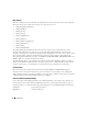
Introduction This reference guide documents the Dell™ OpenManage™ Server Administrator Common Information Model (CIM) provider contained in the Management Object File (MOF) dccim32.mof. CIM provides a conceptual model for describing manageable objects in a systems management environment. CIM is a modeling tool rather than a programming language. CIM provides the structure for organizing objects into a model of a managed environment.
Base Classes The classes listed in the Server Administrator CIM provider class hierarchy do not have a parent property. These base classes do not derive from another class.
The CIM_PackageCurrentSensor monitors an entire physical package, such as all the components contained in a given system chassis. The CIM_PhysicalPackage is dependent on the CIM_PackageCurrentSensor for this monitoring function. Dell-Defined Classes Server Administrator has extended some CIM classes and has created new classes to assist in managing systems and their components.
Common Properties of Classes Many classes have properties such as Caption, Description, and CreationClassName. Table 1-2 defines properties that have the same meaning in every class that has this property and are defined more than once in this guide. Table 1-2. 10 Common Properties of Classes Property Description Data Type Caption Describes the object using a short textual description (one-line string).
Table 1-2. Common Properties of Classes (continued) Property Description Data Type Status Provides a string indicating how well the component is functioning—comparable to "health." Status values for operational and nonoperational conditions include: string Operational Status Values: OK indicates that the object is functioning normally. Degraded means that the item is functioning, but not optimally. Stressed indicates that the element is functioning, but needs attention.
Other Documents You May Need Besides this Dell OpenManage Server Administrator CIM Reference Guide, you can find the following guides either on the Dell Support website at support.dell.com or on the documentation CD: 12 • Server Administrator Online Help is context-sensitive help that you can access while running Server Administrator. Help screens provide step-by-step instructions on how to perform systems management tasks using Server Administrator.
CIM_PhysicalElement CIM_PhysicalElement is a CIM-defined class. The CIM_PhysicalElement class contains the subclasses shown in Figure 2-1. Figure 2-1.
Table 2-1. CIM_PhysicalElement Properties Class Name: CIM_PhysicalElement Parent Class: CIM_ManagedSystemElement Property Description Data Type CreationClassName See Table 1-2, “Common Properties of Classes.” Manufacturer See Table 1-2, “Common Properties of Classes.” Model The name by which the physical element is generally known. string SerialNumber A manufacturer-allocated number used to identify the physical element.
CIM_PhysicalFrame CIM_ManagedSystemElement CIM_PhysicalElement CIM_PhysicalPackage CIM_PhysicalFrame The CIM_PhysicalFrame class described in Table 2-3 contains other frame enclosures such as racks and chassis. Properties like VisibleAlarm or AudibleAlarm, and data related to security breaches are also members of this class. Table 2-3.
Table 2-4.
Table 2-5. DELL_Chassis Properties Class Name: DELL_Chassis Parent Class: CIM_Chassis Property Description Data Type AssetTag Indicates the container AssetTag string. This asset tag string is writable by the system administrator. string SystemClass Refers to the system type that is installed and running the instrumentation.
CIM_PhysicalComponent CIM_ManagedSystemElement CIM_PhysicalElement CIM_PhysicalComponent The CIM_PhysicalComponent class listed in Table 2-6 represents any low-level or basic component within a package. A component object either cannot or does not need to be broken down into its constituent parts. For example, an application specific integrated circuit (ASIC) cannot be broken down into smaller discrete parts. Table 2-6.
Table 2-7.
CIM_PhysicalMemory CIM_ManagedSystemElement CIM_PhysicalElement CIM_PhysicalComponent CIM_Chip CIM_PhysicalMemory The CIM_PhysicalMemory class described in Table 2-8 is a subclass of CIM_Chip, representing lowlevel memory devices, such as SIMMS, DIMMs, and so on. Table 2-8. 20 CIM_PhysicalMemory Properties Class Name: CIM_PhysicalMemory Parent Class: CIM_Chip Property Description Data Type FormFactor See Table 2-7, “CIM_Chip Properties.
Table 2-8. CIM_PhysicalMemory Properties (continued) Class Name: CIM_PhysicalMemory Parent Class: CIM_Chip Property Description MemoryType (continued) 17 SDRAM Data Type 18 SGRAM 19 RDRAM 20 DDR 21 DDR2 DDR2 FB-DIMM TotalWidth Indicates the total width, in bits, of the physical memory, including check or error correction bits. If there are no error correction bits, the value in this property should match that specified for the DataWidth property.
CIM_PhysicalConnector CIM_ManagedSystemElement CIM_PhysicalElement CIM_PhysicalConnector The CIM_PhysicalConnector class explained in Table 2-9 includes physical elements such as plugs, jacks, or buses that connect physical elements. Any object that can be used to connect and transmit signals or power between two or more physical elements is a member of this class. For example, slots and D-shell connectors are types of physical connectors. See Table 2-10 for a list of valid connector type values.
Table 2-10. Connector Type Values 0 Unknown 30 unused 60 Micro-DIN 90 On Board IDE Connector 1 Other 31 unused 61 PS/2 91 On Board Floppy Connector 2 Male 32 IEEE-48 62 Infrared 92 9 Pin Dual Inline 3 Female 33 AUI 63 unused 93 25 Pin Dual Inline 4 Shielded 34 UTP Category 3 64 Access.
CIM_Slot CIM_ManagedSystemElement CIM_PhysicalElement CIM_PhysicalConnector CIM_Slot The CIM_Slot class described in Table 2-11 represents connectors into which packages are inserted. For example, a physical package that is a hard drive can be inserted into a small computer system interface-single connector attachment (SCSI-SCA) slot. As another example, a card can be inserted into a 16-, 32-, or 64-bit expansion slot on a host board. Table 2-11.
CIM_LogicalElement CIM_LogicalElement is a CIM-defined class containing the subclasses shown in Figure 3-1. Figure 3-1.
CIM_SoftwareFeature DELL_SoftwareFeature CIM_SystemResource CIM_IRQ CIM_MemoryMappedIO CIM_DMA CIM_RedundancyGroup CIM_ExtraCapacityGroup DELL_PSRedundancyGroup DELL_FanRedundancyGroup CIM_EnabledLogicalElement CIM_ServiceAccessPoint CIM_RemoteServiceAccessPoint DELL_RemoteServiceAccessPort CIM_LogicalElement CIM_ManagedSystemElement CIM_LogicalElement Table 3-1 lists the following characteristics for members of the CIM_LogicalElement class: • Represent abstractions used to manage and coordinate aspects
CIM_System CIM_ManagedSystemElement CIM_LogicalElement CIM_System The CIM_System class shown in Table 3-2 defines a collection of managed system elements that operates as a functional whole. An instance of the CIM_System class contains a well-defined list of components that work together to perform a specific function. Table 3-2.
DELL_System CIM_ManagedSystemElement CIM_LogicalElement CIM_System CIM_ComputerSystem DELL_System The DELL_System class listed in Table 3-4 is the set of all Dell™ instrumented systems, including server and storage systems. For properties, see Table 3-2, "CIM_System Properties." Table 3-4.
CIM_FRU CIM_ManagedSystemElement CIM_LogicalElement CIM_LogicalDevice CIM_FRU The CIM_FRU class described in Table 3-6 contains manufacturing information related to the Field Replaceable Units (FRU) of a system such as a system planar or I/O riser card. Table 3-6. CIM_FRU Properties Class Name: CIM_FRU Parent Class: CIM_LogicalDevice Property Description Data Type FRUInformationState Indicates the state and availability of FRU information.
Table 3-7. CIM_LogicalPort Properties Class Name: CIM_LogicalPort Parent Class: CIM_LogicalDevice Property Description Data Type Speed Indicates the bandwidth of the port in bits per second. uint64 MaxSpeed Indicates the maximum bandwidth of the port in bits per second. uint64 RequestedSpeed Indicates the requested bandwidth of the port in bits per second. uint64 UsageRestriction Indicates usage parameters for the port.
Table 3-8. CIM_NetworkPort Properties (continued) Class Name: CIM_NetworkPort Parent Class: CIM_LogicalPort Property Description Data Type OtherLinkTechnology When used in conjunction with Link Technology, this property displays relevant links to the device. string PermanentAddress Defines the network address hardcoded into a port. string NetworkAddresses Indicates the network addresses for a port. string FullDuplex Indicates whether the port is operating in a full duplex mode.
Table 3-9. DELL_NetworkPort Properties Class Name: Dell_NetworkPort Parent Class: CIM_NetworkPort Property Description Data Type NicTOECapability Defines NIC TCP Offload Engine (TOE) capability. The following values, with explanations, are possible for this property: uint32 0 - NIC/driver does not support querying for capability. 1 - NIC/driver supports querying for capability but query returned an error. 2 - NIC/driver supports querying for capability and query says it is capable.
Table 3-9. DELL_NetworkPort Properties (continued) Class Name: Dell_NetworkPort Parent Class: CIM_NetworkPort Property Description Data Type IsiSCSIEnable Indicates whether SCSI is enabled. Boolean Indicates NIC /driver status. The following values are possible: uint32 NicStatus 0 - Unknown 1 - Connected 2 - Disconnected 3 - Driver Bad 4 - Driver Disabled 10 - Hardware initializing 11 - Hardware resetting 12 - Hardware closing 13 - Hardware not ready BusNumber Indicates the PCI bus number.
CIM_Sensor CIM_ManagedSystemElement CIM_LogicalElement CIM_LogicalDevice CIM_Sensor CIM_NumericSensor CIM_CurrentSensor The CIM_Sensor class explained in Table 3-10 contains hardware devices capable of measuring the characteristics of some physical property, for example, the temperature or voltage characteristics of a computer system. Table 3-10.
CIM_DiscreteSensor CIM_ManagedSystemElement CIM_LogicalElement CIM_LogicalDevice CIM_Sensor CIM_DiscreteSensor The CIM_DiscreteSensor class described in Table 3-11 has a set of legal string values that it can report. The CIM_DiscreteSensor will always have a "current reading" that corresponds to one of the enumerated values. Table 3-11.
Figure 3-2. Ranges for Threshold Values FATAL CRITICAL UPPER WARNING UPPER User Definable NONCRITICAL NORMAL LOWER User Definable NONCRITICAL WARNING LOWER CRITICAL FATAL Table 3-12 provides definitions for NumericSensor properties. Table 3-12. 36 CIM_NumericSensor Properties Class Name: CIM_NumericSensor Parent Class: CIM_Sensor Property Description Data Type UnitModifier See Table 1-2, "Common Properties of Classes." sint32 CurrentReading See Table 1-2, "Common Properties of Classes.
Table 3-12. CIM_NumericSensor Properties (continued) Class Name: CIM_NumericSensor Parent Class: CIM_Sensor Property Description Data Type UpperThresholdCritical See Table 1-2, "Common Properties of Classes." sint32 SupportedThresholds An array representing the thresholds supported by this sensor.
Table 3-13. CIM_TemperatureSensor Properties Class Name: CIM_TemperatureSensor Parent Class: CIM_NumericSensor Property Description Data Type UnitModifier See Table 1-2, "Common Properties of Classes." sint32 CurrentReading See Table 1-2, "Common Properties of Classes." sint32 IsLinear See Table 1-2, "Common Properties of Classes." Boolean LowerThresholdNonCritical See Table 1-2, "Common Properties of Classes.
CIM_VoltageSensor CIM_ManagedSystemElement CIM_LogicalElement CIM_LogicalDevice CIM_Sensor CIM_NumericSensor CIM_VoltageSensor The CIM_VoltageSensor class shown in Table 3-15 contains sensors that measure voltage and return a value in volts. Table 3-15. CIM_VoltageSensor Properties Class Name: CIM_VoltageSensor Parent Class: CIM_NumericSensor Property Description Data Type UnitModifier See Table 1-2, "Common Properties of Classes.
Table 3-16. CIM_Tachometer Properties Class Name: CIM_Tachometer Parent Class: CIM_NumericSensor Property Description Data Type SensorType See Table 1-2, "Common Properties of Classes." uint16 UnitModifier See Table 1-2, "Common Properties of Classes." sint32 CurrentReading See Table 1-2, "Common Properties of Classes." sint32 IsLinear See Table 1-2, "Common Properties of Classes." Boolean LowerThresholdNonCritical See Table 1-2, "Common Properties of Classes.
Table 3-17. CIM_WatchDog Properties Class Name: CIM_WatchDog Parent Class: CIM_LogicalDevice Property Description MonitoredEntity Indicates the entity that is currently being monitored by the uint16 watchdog feature. This property is used to identify the module that is responsible for rearming the watchdog at periodic intervals.
CIM_Fan CIM_ManagedSystemElement CIM_LogicalElement CIM_LogicalDevice CIM_CoolingDevice CIM_Fan The CIM_Fan class explained in Table 3-19 contains a set of devices that work to keep the ambient internal temperature of the system at a safe value by circulating air. Table 3-19. CIM_Fan Properties Class Name: CIM_Fan Parent Class: CIM_CoolingDevice Property Description Data Type VariableSpeed Specifies whether the fan supports variable speeds.
CIM_PointingDevice CIM_ManagedSystemElement CIM_LogicalElement CIM_LogicalDevice CIM_UserDevice CIM_PointingDevice The CIM_PointingDevice class described in Table 3-21 includes those devices used to point to regions of a display. Examples are a mouse or a trackball. Table 3-21. CIM_PointingDevice Properties Class Name: CIM_PointingDevice Parent Class: CIM_UserDevice Property Description Data Type PointingType Indicates the type of pointing device.
CIM_Keyboard CIM_ManagedSystemElement CIM_LogicalElement CIM_LogicalDevice CIM_UserDevice CIM_Keyboard The CIM_Keyboard class explained in Table 3-22 includes devices that allow users to enter data. Table 3-22. CIM_Keyboard Properties Class Name: CIM_Keyboard Parent Class: CIM_UserDevice Property Description Data Type NumberOfFunctionKeys Indicates the number of function keys on the keyboard. uint16 Layout A free-form string indicating the format and layout of the keyboard.
Table 3-23. CIM_PowerSupply Properties Class Name: CIM_PowerSupply Parent Class: CIM_LogicalDevice Property Description Data Type IsSwitchingSupply Indicates that the power supply is a switching power supply and not a linear power supply. Boolean Range1InputVoltageLow Indicates the low voltage in millivolts of input voltage range 1 for uint32 this power supply. A value of 0 denotes unknown.
Table 3-24. CIM_Controller Properties Class Name: CIM_Controller Parent Class: CIM_LogicalDevice Property Description Data Type ProtocolSupported The protocol used by the controller to access controlled devices.
CIM_SerialController CIM_ManagedSystemElement CIM_LogicalElement CIM_LogicalDevice CIM_Controller CIM_SerialController The CIM_SerialController class explained in Table 3-26 contains controllers that transfer data one bit at a time to the devices they control, for example, a serial port controlling a modem. Table 3-26.
Table 3-27. CIM_PCIController Properties Class Name: CIM_PCIController Parent Class: CIM_Controller Property Description CommandRegister The current contents of the register that provides basic control over the uint16 device’s ability to respond to, and/or perform PCI accesses. The data in the capabilities array is gathered from the PCI status register and the PCI capabilities list as defined in the PCI specification.
Table 3-28. CIM_PCIDevice Properties Class Name: CIM_PCIDevice Parent Class: CIM_PCIController Property Description Data Type BaseAddress Identifies an array of up to six double-word base memory addresses. uint32 SubsystemID Identifies a subsystem identifier code. uint16 SubsystemVendorID Identifies a subsystem vendor ID. ID information is reported uint16 from a PCI device via protocol-specific requests.
Table 3-29. CIM_PCIBridge Properties Class Name: CIM_PCIBridge Parent Class: CIM_PCIController Property Description Data Type BaseAddress Identifies an array of double-word base memory addresses. uint32 BridgeType Indicates the type of bridge. A bridge is PCI to , except for the Host, which is a host-to-PCI bridge. Values for the BridgeType property are as follows: 0 Host 1 ISA 128 Other uint16 BaseAddress Identifies an array of double-word base memory addresses.
Table 3-30. CIM_Processor Properties Class Name: CIM_Processor Parent Class: CIM_LogicalDevice Property Description Data Type Role A string describing the role of the microprocessor, for example, central microprocessor or math processor. string UpgradeMethod Provides microprocessor socket information including data on how this uint16 microprocessor can be upgraded (if upgrades are supported). This property is an integer enumeration.
Table 3-30. CIM_Processor Properties (continued) Class Name: CIM_Processor Parent Class: CIM_LogicalDevice Property Description ExtendedCharacteristics Indicates the extended capabilities of the processor. This attribute is a bit field.
Table 3-30. CIM_Processor Properties (continued) Class Name: CIM_Processor Parent Class: CIM_LogicalDevice Property Description Data Type Family Refers to the processor family type.
Table 3-30.
Table 3-30.
Table 3-30.
CIM_StorageExtent CIM_ManagedSystemElement CIM_LogicalElement CIM_LogicalDevice CIM_StorageExtent CIM_StorageExtent identified in Table 3-31 contains devices that manage data storage, for example, hard drives or microprocessor memory. Table 3-31.
CIM_CacheMemory CIM_ManagedSystemElement CIM_LogicalElement CIM_LogicalDevice CIM_StorageExtent CIM_Memory CIM_CacheMemory The CIM_CacheMemory class explained in Table 3-33 describes the capabilities and management of cache memory. Cache memory allows a microprocessor to access data and instructions faster than normal system memory. Table 3-33.
Table 3-33. CIM_CacheMemory Properties (continued) Class Name: CIM_CacheMemory Parent Class: CIM_Memory Property Description CacheType Defines whether this cache is for instruction caching, data caching, or both uint16 (unified). Values for the CacheType property are as follows: 1 Other 2 Unknown 3 Instruction 4 Data 5 Unified LineSize Indicates the size, in bytes, of a single cache bucket or line. uint32 ReadPolicy Defines the policy used by the cache for handling read requests.
Table 3-34. CIM_SoftwareElement Properties Class Name: CIM_SoftwareElement Parent Class: CIM_LogicalElement Property Description Data Type Name Indicates the name that identifies this software element. string Version Provides the version in the form .. or .; for example, 1.2.3 or 1.2a3. string Manufacturer See Table 1-2, "Common Properties of Classes.
CIM_SoftwareFeature CIM_ManagedSystemElement CIM_LogicalElement CIM_SoftwareFeature The CIM_SoftwareFeature class shown in Table 3-36 defines a particular function or capability of a product or application system. This class is intended to be meaningful to a consumer, or user of a product, rather than to explain how the product is built or packaged.
DELL_SoftwareFeature described in Table 3-37 defines the universal resource locator (URL) of the systems management software and the language in which systems management information displays. Defining these properties enables users to manage a system using an Internet browser. You can access Server Administrator using the secure hypertext transfer protocol (https) and a preassigned port number of 1311, or you can specify a port number of your own choosing. Table 3-37.
The CIM_IRQ class described in Table 3-39 contains IRQ information. An IRQ is a signal that data is about to be sent to or received by a peripheral device. The signal travels by an IRQ line to the microprocessor. Each peripheral connection must be assigned an IRQ number. For example, the first serial port in your computer (COM1) is assigned to IRQ4 by default. Table 3-39.
Table 3-39. 64 CIM_IRQ Properties (continued) Class Name: CIM_IRQ Parent Class: CIM_SystemResource Property Description Hardware Indicates whether the interrupt is hardware- or software-based. (A Boolean value of TRUE indicates that the interrupt is hardware based.) On a personal computer, a hardware IRQ is a physical wire to a programmable interrupt controller (PIC) chip set through which the microprocessor can be notified of time critical events.
CIM_MemoryMappedIO CIM_ManagedSystemElement CIM_LogicalElement CIM_SystemResource CIM_MemoryMappedIO The CIM_MemoryMappedIO class explained in Table 3-40 addresses both memory and port I/O resources for personal computer architecture memory mapped I/O. Table 3-40. CIM_MemoryMappedIO Properties Class Name: CIM_MemoryMappedIO Parent Class: CIM_SystemResource Property Description Data Type CSCreationClassName See Table 1-2, "Common Properties of Classes.
CIM_DMA CIM_ManagedSystemElement CIM_LogicalElement CIM_SystemResource CIM_DMA The CIM_DMA class explained in Table 3-41 contains DMA information. A DMA channel allows certain types of data transfer between RAM and a device to bypass the microprocessor. Table 3-41. 66 CIM_DMA Properties Class Name: CIM_DMA Parent Class: CIM_SystemResource Property Description Data Type CSCreationClassName See Table 1-2, "Common Properties of Classes.
CIM_RedundancyGroup CIM_ManagedSystemElement CIM_LogicalElement CIM_RedundancyGroup The CIM_RedundancyGroup class explained in Table 3-42 is a set of components that provide more instances of a critical component than are required for the system’s operation. The extra components are used in case of critical component failure. For example, multiple power supplies allow a working power supply to take over when another power supply has failed. Table 3-42.
CIM_ExtraCapacityGroup CIM_ManagedSystemElement CIM_LogicalElement CIM_RedundancyGroup CIM_ExtraCapacityGroup The CIM_ExtraCapacityGroup class explained in Table 3-43 applies to systems that have more capability and components than are required for normal operation, for example, systems that have extra fans or power supplies. Table 3-43.
DELL_FanRedundancyGroup CIM_ManagedSystemElement CIM_LogicalElement CIM_RedundancyGroup CIM_ExtraCapacityGroup DELL_FanRedundancyGroup The DELL_FanRedundancyGroup described in Table 3-45 defines what constitutes fan redundancy in a system. Table 3-45.
CIM_ServiceAccessPoint CIM_ManagedSystemElement CIM_LogicalElement CIM_EnabledLogicalElement CIM_ServiceAccessPoint The CIM_ServiceAccessPointGroup class described in Table 3-47 represents the ability to utilize or invoke a service. Access points indicate that a service is available to other entities for use. Table 3-47.
Table 3-48. CIM_RemoteServiceAccessPointGroup Properties Class Name: CIM_RemoteServiceAccessPointGroup Parent Class: CIM_ServiceAccessPointGroup Property Description AccessInfo Describes accessing or addressing of information for a remote connection. string This can be a host name, network address, and other similar information. InfoFormat Indicates an enumerated integer describing the format and interpretation uint16 of the AccessInfo property.
DELL_RemoteServiceAccessPort CIM_ManagedSystemElement CIM_LogicalElement CIM_EnabledLogicalElement CIM_ServiceAccessPoint CIM_RemoteServiceAccessPoint DELL_RemoteServiceAccessPort The DELL_RemoteServiceAccessPortGroup class described in Table 3-49 is an extended class of the CIM_RemoteServiceAccessPointGroup class. The DELL_RemoteServiceAccessPortGroup class provides information about Dell implementation-specific attributes. Table 3-49.
Dell-Defined Classes The Dell-defined classes are defined and populated by Dell™ rather than by CIM. None of these classes have a parent class and are on the same level as CIM_ManagedSystemElement. For information on how the logs are formatted, see Table 2-5, “DELL_Chassis Properties.” DELL_EsmLog CIM_ManagedSystemElement DELL_EsmLog The DELL_EsmLog class described in Table 4-1 records failure threshold violations collected by Server Administrator’s embedded server management (ESM) capabilities.
DELL_PostLog CIM_ManagedSystemElement DELL_PostLog The DELL_PostLog identified in Table 4-2 is a record of the system’s power-on self-test (POST). When you turn on a system, the POST tests various system components, such as random-access memory (RAM), the hard drives, and the keyboard. Table 4-2. DELL_PostLog Properties Class Name: DELL_PostLog Parent Class: None DELL_CMApplication NOTE: Dell-updateable components, such as BIOS and FW, are considered applications.
DELL_CMDevice CIM_ManagedSystemElement DELL_CMDevice The DELL_CMDevice identified in Table 4-4 contains information related to the Dell Change Management device. Table 4-4.
Table 4-5. DELL_CMDeviceApplication Properties Class Name: DELL_CMDeviceApplication Parent Class: None Property Description Data Type antecedent Refers to the device string dependent Refers to the application string DELL_CMInventory CIM_ManagedSystemElement DELL_CMInventory The DELL_CMInventory identified in Table 4-6 contains information related to the Dell Change Management inventory. Table 4-6.
Table 4-7.
Management Object File For Change Management The following shows the Management Object File (MOF) invcim.mof. #pragma classflags("forceupdate") #pragma namespace("\\\\.\\Root\\CIMV2") [Locale(1033) : ToInstance] Instance of __Namespace { Name = "Dell"; }; #pragma namespace ("\\\\.
instance of __MethodProviderRegistration { Provider = $P; }; //core.mof //============================================ // Using my own MOF instead of inheriting from existing MOFs, for rapid prototyping. // ============================================ [Dynamic, Provider ("omprov"), Description("The Dell_CMDevice class contains all the the information related to the Dell Change Management Device.
[write (true), key: ToSubClass] string function; }; [Dynamic, Provider ("omprov"), Description("The Dell_CMInventory class contains all the information related to the Dell Change Management Inventory.
[Dynamic, Provider ("omprov"), Description("The Dell_CMOS class contains all the information related to the Dell Change Management operating system.
string version; [write (true), key: ToSubClass] string name; [write (true), key: ToSubClass] string deviceKey; }; [Association, Dynamic, Provider ("omprov"), Description("The Dell_CMDeviceApplication class contains all the information related to the Dell Change Management association between the device and the application (1:n).") ] class Dell_CMDeviceApplication { [key, Override ("Antecedent"), Description ("The Device.
CIM_Dependency The CIM_Dependency class is an association used to establish dependency relationships between two managed system elements. CIM_Dependency shown in Figure 5-1 does not have a parent class because it is a relationship or association between two elements. Figure 5-1.
Table 5-1. DELL_FanSensor Properties Class Name: DELL_FanSensor Parent Class: CIM_Dependency Element Description Antecedent CIM_Tachometer refers to the tachometer (fan sensor) that measures the RPM of the fan. Dependent CIM_Fan refers to the fan whose revolutions are measured by the tachometer.
CIM_PackageVoltSensor CIM_ManagedSystemElement CIM_Dependency CIM_PackageVoltSensor The CIM_PackageVoltSensor identified in Table 5-3 contains voltage sensors that are often installed in a package such as a chassis or a rack to assist in the monitoring of the package in general. This relationship is described by the CIM_PackageVoltSensor association. Table 5-3.
CIM_PackageFanSensor CIM_ManagedSystemElement CIM_Dependency CIM_PackageFanSensor The CIM_PackageFanSensor class described in Table 5-5 contains fan sensors that monitor the whole package. Table 5-5. CIM_PackageFanSensor Properties Class Name: CIM_PackageFanSensor Parent Class: CIM_Dependency Element Description Antecedent CIM_Fan refers to the cooling device for the package. Dependent CIM_PhysicalPackage refers to the physical package whose environment is being monitored.
DELL_PackagePSRedundancy CIM_ManagedSystemElement CIM_Dependency DELL_PackagePSRedundancy The DELL_PackagePSRedundancy class listed in Table 5-7 defines what constitutes power supply redundancy for an entire package. Table 5-7. DELL_PackagePSRedundancy Properties Class Name: DELL_PackagePSRedundancy Parent Class: CIM_Dependency Element Description Antecedent DELL_PSRedundancyGroup refers to power supplies that deliver wattage for the entire package.
DELL_PSRedundancy CIM_ManagedSystemElement CIM_Dependency DELL_PSRedundancy The DELL_PSRedundancy class shown in Table 5-8 defines what constitutes power supply redundancy for Dell™ systems. Table 5-8. 88 DELL_PSRedundancy Properties Class Name: DELL_PSRedundancy Parent Class: CIM_Dependency Element Description Antecedent CIM_PowerSupplySensor refers to the power supply sensor that monitors wattage for the entire package.
Glossary The following list defines or identifies technical terms, abbreviations, and acronyms used in user documents. asset tag code class An individual code assigned to a computer, usually by a system administrator, for security or tracking purposes. For the purposes of the Dell™ CIM provider, a class is a set of managed system elements that can be monitored and managed using a systems management console capable of receiving CIM information.
DMTF property Abbreviation for Distributed Management Task Force, a consortium of companies representing hardware and software providers. A property is a capability or characteristic of a CIM class. The temperature probe class, for example, has a property that describes its thresholds for normal, lower critical, and upper critical ranges of operation.
RAID unattended installation Acronym for redundant array of independent disks. An unattended installation requires far less operator involvement than an interactive installation. Also called a “silent installation,” unattended installation programs record the administrator’s preferences about which features of an application program to install. The file that records these installation feature preferences is called a “response file” or an “answer file.
Glossary
Index C CIM classes and properties, 7 base classes, 8 classes that describe relationships, 8 common properties of classes, 10 conventions, 9 parent classes, 8 CIM_Chip, 18 CIM_Dependency CIM_PackageCurrentSensor, 85 CIM_PackageFanSensor, 86 CIM_PackagePowerSupplySen sor, 86 CIM_PackageTempSensor, 84 CIM_PackageVoltSensor, 85 DELL_FanSensor, 83 DELL_PackagePSRedundancy , 87 DELL_PSRedundancy, 88 CIM_LogicalElement CIM_BIOSElement, 59 CIM_CacheMemory, 58 CIM_ComputerSystem, 27 CIM_Controller, 45 CIM_CoolingDe
Index DELL_CMInventory, 76 DELL_CMOS, 76 DELL_CMProductInfo, 77 DELL_EsmLog, 73 DELL_PostLog, 74 DELL_PSRedundancy, 88 description, 9 P parent class, 9 property, 9 S Server Administrator 1.