Dell OptiPlex 790 Small Form Factor Owner's Manual Regulatory Model D03S Regulatory Type D03S001
Notes, Cautions, and Warnings NOTE: A NOTE indicates important information that helps you make better use of your computer. CAUTION: A CAUTION indicates potential damage to hardware or loss of data if instructions are not followed. WARNING: A WARNING indicates a potential for property damage, personal injury, or death. Information in this publication is subject to change without notice. © 2011 Dell Inc. All rights reserved.
Contents Notes, Cautions, and Warnings..................................................................2 1 Working on Your Computer......................................................................7 Before Working Inside Your Computer.............................................................................7 Recommended Tools.........................................................................................................8 Turning Off Your Computer.............................................
Installing The Memory.....................................................................................................22 8 Chassis Intrusion Switch........................................................................23 Removing the Chassis Intrusion Switch..........................................................................23 Installing The Intrusion Switch.......................................................................................24 9 Speaker........................................
16 System Board..........................................................................................45 Removing the System Board...........................................................................................45 Installing The System Board...........................................................................................47 17 Drive Cage...............................................................................................49 Removing the Drive Cage.............................
Working on Your Computer 1 Before Working Inside Your Computer Use the following safety guidelines to help protect your computer from potential damage and to help to ensure your personal safety. Unless otherwise noted, each procedure included in this document assumes that the following conditions exist: • • You have read the safety information that shipped with your computer. A component can be replaced or--if purchased separately--installed by performing the removal procedure in reverse order.
To avoid damaging your computer, perform the following steps before you begin working inside the computer. 1. Ensure that your work surface is flat and clean to prevent the computer cover from being scratched. 2. Turn off your computer (see Turning Off Your Computer). CAUTION: To disconnect a network cable, first unplug the cable from your computer and then unplug the cable from the network device. 3. Disconnect all network cables from the computer. 4.
Click Start , then click the arrow in the lower-right corner of the Start menu as shown below, and then click Shut Down. • 2. In Windows XP: Click Start → Turn Off Computer → Turn Off . The computer turns off after the operating system shutdown process is complete. Ensure that the computer and all attached devices are turned off.
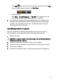
Cover 2 Removing the Cover 1. Follow the procedures in Before Working Inside Your Computer. 2. Pull up the cover-release latch at the side of the computer. 3. Lift the cover upward to a 45–degree angle and remove it from the computer. Installing The Cover 1. Place the computer cover on the chassis. 2. Press down on the computer cover, until it clicks into place. 3. Follow the procedures in After Working Inside Your Computer.
Front Bezel 3 Removing the Front Bezel 1. Follow the procedures in Before Working Inside Your Computer. 2. 3. Remove the cover. Pry the front bezel retention clips away from the chassis. 4. Rotate the bezel away from the computer to release the hooks on the opposite edge of the bezel from the chassis.
Installing The Front Bezel 1. 3. Insert the four hooks along the bottom edge of the front bezel into the slots on the chassis front. Rotate the bezel toward the computer to engage the front bezel retention clips until they click into place. Install the cover. 4. Follow the procedures in After Working Inside Your Computer. 2.
Expansion Card 4 Removing the Expansion Card 1. Follow the procedures in Before Working Inside Your Computer. 2. Remove the cover. 3. Remove the front bezel. 4. Rotate the release tab on the card-retention latch upward. 5. Pull the release lever away from the PCIe x16 card until you release the securing tab from the dent in the card. Then, ease the card up and out of its connector and remove it from the computer. 6.
Installing The Expansion Card 1. 3. Insert the PCIe x4 card into the connector on the system board and press down to secure it in place. Insert the PCIe x16 card (if any) into the connector on the system board and press down to secure it in place. Install the front bezel. 4. 5. Install the cover. Follow the procedures in After Working Inside Your Computer. 2.
Optical Drive 5 Removing the Optical Drive 1. Follow the procedures in Before Working Inside Your Computer. 2. 3. Remove the cover. Remove the data cable and power cable from the back of the optical drive. 4. Lift the blue tab and slide the optical drive inwards to remove it from the computer. 5. Remove the optical drive from the bracket.
Installing The Optical Drive 1. 2. 3. 4. Insert the optical drive into the bracket. Lift the blue tab and slide the optical drive outwards to insert it into the computer. Connect the data cable and power cable to the optical drive. Install the cover. 5. Follow the procedures in After Working Inside Your Computer.
Hard Drive 6 Removing the Hard Drive 1. Follow the procedures in Before Working Inside Your Computer. 2. Remove the cover. 3. Remove the hard drive from the chassis. 4. Press the retention clips inwards and slide the hard-drive bracket from the drive cage. 5. Flex the hard-drive bracket and then remove the single 3.5 inch hard drive or two 2.5 inch hard drives from the bracket. 6. Release the screws that secure the 2.5 inch hard drive to the top of the hard-drive bracket.
7. Release the screws that secure the 2.5 inch hard drive to the underside of the hard-drive bracket. Installing The Hard Drive 1. 4. Tighten the screws to secures the two hard drives to the hard drive bracket. Flex the hard-drive bracket and then insert the single hard drive or two hard drives into the bracket. Press the retention clips inwards and slide the hard-drive bracket into the drive cage. Install the cover. 5. Follow the procedures in After Working Inside Your Computer. 2. 3.
Memory 7 Removing the Memory 1. Follow the procedures in Before Working Inside Your Computer. 2. 3. 4. 5. Remove the cover. Remove the front bezel. Remove the drive cage. Release the memory-retention clips on each side of the memory modules. 6. Lift the memory modules out of the connectors on the system board.
Installing The Memory 1. 3. Insert the memory modules into the connectors on the system board. Install the memory modules in the order of A1 > B1 > A2 > B2. Press down on the memory modules until the retention clips spring back to secure them in place. Install the drive cage. 4. 5. 6. Install the front bezel. Install the cover. Follow the procedures in After Working Inside Your Computer. 2.
Chassis Intrusion Switch 8 Removing the Chassis Intrusion Switch 1. Follow the procedures in Before Working Inside Your Computer. 2. 3. Remove the cover. Disconnect the intrusion-switch cable from system board. 4. Slide the intrusion switch inwards and remove it from the system board.
Installing The Intrusion Switch 1. 2. 3. Insert the intrusion switch into the chassis rear and slide it outward to secure it. Connect the intrusion-switch cable to the system board. Install the cover. 4. Follow the procedures in After Working Inside Your Computer.
Speaker 9 Removing the Speaker 1. Follow the procedures in Before Working Inside Your Computer. 2. Remove the cover. 3. Remove the front bezel. 4. Remove the drive cage. 5. Disconnect the speaker cable from the system board. 6. Unthread the speaker cable from the fan shelter clip. 7. Press the speaker securing tab, and slide the speaker towards the right of the computer to release it.
8. Remove the speaker from the chassis. Installing The Speaker 1. Place the speaker on the appropriate location of the chassis rear. 2. Press the speaker-securing tab and slide the speaker towards the left of the computer to secure it. 3. Thread the internal speaker cable into the fan shelter clip. 4. Connect the speaker cable to the system board. 5. Install the drive cage. 6. Install the front bezel. 7. Install the cover. 8. Follow the procedures in After Working Inside Your Computer.
Heat Sink And Processor 10 Removing the Heat Sink and Processor 1. Follow the procedures in Before Working Inside Your Computer. 2. Remove the cover. 3. Remove the front bezel. 4. Remove the drive cage. 5. Disconnect the heat-sink assembly cable from the system board. 6. Release the Input/Output Board or the FlyWire cable from the routing channel on the heat sink. 7. Loosen the captive screws in the order of 1,2,3 and 4.
8. Lift the heat sink assembly upwards, and remove it from the computer. Lay the assembly with the fan facing downwards, and with the thermal grease facing upwards. 9. Press the release lever down and then move it outward to release it from the retention hook that secures it. 10. Lift the processor cover.
11. Lift the processor to remove it from the socket and place it in an antistatic package.
Installing The Heat Sink And Processor 1. 2. 3. 4. 5. 6. 7. 8. Insert the processor into the processor socket. Ensure the processor is properly seated. Lower the processor cover. Press the release lever down and then move it inward to secure it with the retention hook. Place the heat sink assembly into the chassis. Tighten the captive screws to secure the heat-sink assembly to the system board. Secure the Input/Output Board or the FlyWire cable to the routing channel on the heat sink.
Coin-Cell Battery 11 Removing the Coin-Cell Battery 1. Follow the procedures in Before Working Inside Your Computer. 2. 3. 4. Remove the cover. Remove the front bezel. Press the coin-cell battery inward to allow the battery to pop up from the socket. 5. Lift the coin-cell battery out of the computer.
Installing The Coin-Cell Battery 1. 2. 3. Place the coin-cell battery into its slot on the system board. Press the coin-cell battery downwards till it is secured. Install the front bezel. 4. 5. Install the cover. Follow the procedures in After Working Inside Your Computer.
Power-Switch Cable 12 Removing the Power-Switch Cable 1. Follow the procedures in Before Working Inside Your Computer. 2. Remove the cover. 3. Remove the front bezel. 4. Remove the drive cage. 5. Disconnect the power-switch cable from the system board. 6. Unthread the power-switch cable from the chassis clip. 7. Pry the power-switch cable away from the chassis.
8. Slide the power-switch cable out through the front of the computer. Installing the Power-Switch Cable 1. 2. 3. 4. 5. Slide the power-switch cable in through the front of the computer. Secure the power-switch cable to the chassis. Thread the power-switch cable into the chassis clip. Connect the power-switch cable to the system board. Install the drive cage. 6. 7. 8. Install the front bezel. Install the cover. Follow the procedures in After Working Inside Your Computer.
System Fan 13 Removing the System Fan 1. Follow the procedures in Before Working Inside Your Computer. 2. Remove the cover. 3. Remove the front bezel. 4. Remove the drive cage. 5. Remove the fan shelter. 6. Disconnect the fan cable from the system board. 7. Slide the grommets inward along the groove and pass through the chassis. 8. Lift and remove the system fan from the computer.
9. Pry up the grommets from the system fan and remove it. Installing The System Fan 1. Insert the four grommets into the system fan. 2. Place the system fan in the chassis. 3. Pass the four grommets through the chassis and slide outward along the grooves to secure them in place. 4. Connect the fan cable to the system board. 5. Install the fan shelter. 6. Install the drive cage. 7. Install the front bezel. 8. Install the cover. 9.
Input/Output Panel 14 Removing The Input/Output (I/O) Panel 1. Follow the procedures in Before Working Inside Your Computer. 2. Remove the cover. 3. Remove the front bezel. 4. Remove the drive cage. 5. Unthread the I/O panel or the FlyWire cable from the fan-shelter clip and heat sink. 6. Disconnect the I/O panel or the FlyWire cable from the system board. 7. Remove the single screw that secures the I/O panel to the chassis.
8. Slide the I/O panel towards the right of the computer to release it from the chassis. 9. Remove the I/O panel.
Installing The Input/Output (I/O) Panel 1. 2. 6. Insert the I/O panel into the slot on the chassis front. Slide the I/O panel towards the left of the computer to secure to the chassis. Tighten the screw to secure the I/O panel to the chassis. Connect the I/O panel or the FlyWire cable to the system board. Thread the I/O panel or the FlyWire cable into the fan-shelter clip and the routing on the heat sink. Install the drive cage. 7. 8. 9. Install the front bezel. Install the cover.
Power Supply 15 Removing the Power Supply 1. Follow the procedures in Before Working Inside Your Computer. 2. Remove the cover. 3. Remove the front bezel. 4. Remove the drive cage. 5. Remove the fan shelter. 6. Disconnect the 4-pin power cable from the system board. 7. Unthread the 4–pin power cable from the chassis clips. 8. Disconnect the 24-pin power cable from the system board.
9. Remove the screws that secure the power supply, from the back of the computer. 10. Push in on the blue release tab beside the power supply, and slide the power supply towards the front of the computer. 11. Lift the power supply out of the computer.
Installing The Power Supply 1. 2. 3. 4. 5. 6. Place the power supply in the chassis and slide outward to secure it. Tighten the three screws securing the power supply to the back of the computer. Connect the power cable to the system board. Thread the power cable into the chassis clips. Connect the power cable to the system board. Install the fan shelter. 7. 8. 9. 10. Install the drive cage. Install the front bezel. Install the cover. Follow the procedures in After Working Inside Your Computer.
System Board 16 Removing the System Board 1. Follow the procedures in Before Working Inside Your Computer. 2. Remove the cover. 3. Remove the front bezel. 4. Remove the drive cage. 5. Remove the expansion cards. 6. Remove the heat sink and processor. 7. Remove the fan shelter. 8. Disconnect all the cables connected to the system board, and move the cables away from the chassis. 9. Lift and release the expansion-card latch, to gain access to the screws securing the system board.
10. Remove the screws that secure the system board to the chassis. 11. Remove the 7–mm hex screw that secures the system board to the chassis. 12. Slide the system board towards the front of the computer. 13. Remove the system board from the chassis.
Installing The System Board 1. Align the system board to the port connectors on the rear of the chassis and place the system board in the chassis. 2. Tighten the 7–mm hex screw securing the system board to the chassis. 3. Tighten the screws securing the system board to the chassis. 4. Close the expansion card latch. 5. Connect the cables to the system board. 6.
Drive Cage 17 Removing the Drive Cage 1. Follow the procedures in Before Working Inside Your Computer. 2. 3. 4. Remove the cover. Remove the front bezel. Remove the data cable and power cable from the back of the optical drive. 5. Slide the drive-cage handle toward the back of the computer into the unlocked position. 6. Rotate the drive cage upward using the handle and lift the drive cage free off the chassis.
7. Remove the data cable and power cable from the back of the hard drive. 8. Remove the drive cage from the computer.
Installing The Drive Cage 1. 5. 6. Place the drive cage on the edge of the computer to allow access to the cable connectors on the hard drive. Connect the data cable and power cable to the back of the hard drive. Flip over the drive cage and insert it into the chassis. The drive cage tabs are secured by the slots in the chassis. Slide the drive-cage handle toward the front of the computer into the locked position. Connect the data cable and power cable to the back of the optical drive.
Fan Shelter 18 Removing the Fan Shelter 1. Follow the procedures in Before Working Inside Your Computer. 2. Remove the cover. 3. Unthread the cables in the fan shelter clip. 4. Lift the fan shelter free from the computer. Installing The Fan Shelter 1. Insert the fan shelter into the computer. 2. Thread the cables into the fan shelter clip. 3. Install the cover. 4. Follow the procedures in After Working Inside Your Computer.
System Setup 19 System Setup This computer offers you the following options: • • Access System Setup by pressing Bring up a one-time boot menu by pressing Press to enter System Setup and make changes to the user-definable settings. If you have trouble entering System Setup using this key, press when the keyboard LEDs first flash.
When you enter the or keystroke correctly, the computer beeps. The key sequence invokes the Boot Device Menu. Since the one-time boot menu only affects the current boot, it has the added benefit of not requiring the technician to restore the customer's boot order after completing troubleshooting. Timing Key Sequences The keyboard is not the first device initialized by Setup. As a result, if you press a keystroke too early, you lock out the keyboard.
Action Keystroke Expand and collapse field , left- or right-arrow key, or +/– Expand or collapse all fields <> Exit BIOS — Remain in Setup, Save/Exit, Discard/Exit Change a setting Left or right-arrow key Select field to change Cancel modification Reset defaults or Load Defaults menu option System Setup Options NOTE: Depending on the computer and its installed devices, the items listed in this section may or may not appear.
General • • SATA CD/DVD/CD-RW Drive Boot List Option • • Legacy UEFI Date/Time Allows you to set the date and time. Changes to the system date and time take effect immediately. System Configuration Integrated NIC Allows you to enable or disable the integrated network card. You can set the integrated NIC to: • • • • Disabled Enabled (default) Enabled w/PXE Enabled w/ImageServer NOTE: Depending on the computer and its installed devices, the items listed in this section may or may not appear.
System Configuration • Drives Disabled = The SATA controller is hidden Allows you to enable or disable the various on-board drives: • • • • SATA-0 SATA-1 SATA-2 SATA-3 Smart Reporting This field controls whether hard drive errors for integrated drives are reported during system startup. This technology is part of the SMART (Self Monitoring Analysis and Reporting Technology) specification. This option is disabled by default. USB Configuration This field configures the integrated USB controller.
Video NOTE: The Video setting will only be visible when a video card is installed in the system. Security Internal HDD-1 Password Allows you to set, change, or delete the password on the system's internal hard disk drive (HDD). Successful changes to this password take effect immediately. By default, the drive will not have a password set • • • Strong Password Enter the old password Enter the new password Confirm new password This field enforces strong passwords.
Security Allow Non-Admin Password Changes — This option is enabled by default. Non-Admin Setup Changes This option lets you determine whether changes to the setup option are permitted when an administrator password is set. Allow Wireless Switch Changes — This option is disabled by default. TPM Security This option lets you control whether the Trusted Platform Module (TPM) in the system is enabled and visible to the operating system. TPM Security — This option is disabled by default.
Security • • • Enable — User may enter OROM configuration screens via the hotkey. One-Time Enable — User may enter OROM configuration screens via the hotkeys on next boot only. After next boot, the setting will revert to disabled. Disable — User may not enter OROM configuration screens via the hotkey. This option is set to Enable by default. Admin Setup Lockout Allows you to enable or disable the option to enter Setup when an Admin password is set. This option is not set by default.
Power Management • • Auto On Time Power On Last State Allows you to set the option to automatically turn on the computer. Time is kept in standard 12-hour format (hour:minutes:seconds). Change the startup time by typing the values in the time and AM/PM fields. NOTE: This feature does not work if you turn off your computer using the switch on a power strip or surge protector or if Auto Power is set to disabled. Deep Sleep Control Allows you to define the controls when Deep Sleep is enabled.
POST Behavior Keyboard Errors Allows you to enable or disable the keyboard error reporting when the computer starts. This option is enabled by default. POST Hotkeys Allows you to specify the function keys to display on the screen when the computer starts.
Image Server Lookup Method Specifies how the ImageServer looks up the server address. • • Static IP DNS (enabled by default) NOTE: This field is only relevant when the "Integrated NIC" control in the "System Configuration" group is set to "Enabled with ImageServer". ImageServer IP Specifies the primary static IP address of the ImageServer with which the client software communicates. The default IP address is 255.255.255.255.
Image Server NOTE: This field is only relevant when the "Integrated NIC" control in the "System Configuration" group is set to "Enabled with ImageServer" and when "Client DHCP" is set to "Static IP". Client Gateway Specifies the gateway IP address for the client. The default setting is 255.255.255.255. NOTE: This field is only relevant when the "Integrated NIC" control in the "System Configuration" group is set to "Enabled with ImageServer" and when "Client DHCP" is set to "Static IP".
Troubleshooting 20 Diagnostic LEDs NOTE: The diagnostic LEDs only serve as an indicator of the progress through the Power-on Self-Test (POST) process. These LEDs do not indicate the problem that caused the POST routine to stop. The diagnostic LEDs are located on the front of the chassis next to the power button. These diagnostic LEDs are only active and visible during the POST process. Once the operating system starts to load, they turn off and are no longer visible.
• Ensure that the main power cable and front panel cable are securely connected to the system board. LED Power Button Problem Description A possible system board failure has occurred. Troubleshooting Steps Unplug the computer. Allow one minute for the power to drain. Plug the computer into a working electrical outlet and press the power button. LED Power Button Problem Description A possible system board, power supply, or peripheral failure has occurred.
LED Power Button Problem Description Memory modules are detected, but a memory power failure has occurred. Troubleshooting Steps • • If two or more memory modules are installed, remove the modules, then re-install one module and re-start the computer. If the computer starts normally, continue to install additional memory modules (one at a time) until you have identified a faulty module or reinstalled all modules without error.
add the peripheral cards back one by one until you find the bad one. LED Power Button Problem Description Power connector not installed properly. Troubleshooting Steps Re-seat the 2x2 power connector from the power supply unit. LED Power Button Problem Description Possible peripheral card or system board failure has occurred. Troubleshooting Steps Remove all peripheral cards from the PCI and PCI-E slots and re-start the computer.
• If the problem persists, the system board is faulty. LED Power Button Problem Description A possible coin cell battery failure has occurred. Troubleshooting Steps Remove the coin cell battery for one minute, reinstall the battery, and restart. LED Power Button Problem Description A possible processor failure has occurred. Troubleshooting Steps Re-seat the processor. LED Power Button Problem Description Memory modules are detected, but a memory failure has occurred.
• If available, install working memory of the same type into your computer. LED Power Button Problem Description A possible hard drive failure has occurred. Troubleshooting Steps Re-seat all power and data cables. LED Power Button Problem Description A possible USB failure has occurred. Troubleshooting Steps Re-install all USB devices and check all cable connections. LED Power Button Problem Description No memory modules are detected.
• If available, install working memory of the same type into your computer. LED Power Button Problem Description Memory modules are detected, but a memory configuration or compatibility error has occurred. Troubleshooting Steps • • Ensure that no special requirements for memory module/connector placement exist. Ensure that the memory you are using is supported by your computer. LED Power Button Problem Description A possible expansion card failure has occurred.
Power Button Problem Description A possible system board resource and/or hardware failure has occurred. Troubleshooting Steps • • • Clear CMOS. Disconnect all internal and external peripherals, and restart the computer. If the computer boots, add the peripheral cards back one by one until you find the bad one. If the problem persists, the system board / system board component is faulty. LED Power Button Problem Description Some other failure has occurred.
each set of beeps is 3 sec, and the beep sound lasts 300 ms. After each beep and each set of beeps, the BIOS should detect if the user presses the power button. If so, BIOS will jump out from looping and execute the normal shutdown process and power system.
Code 3-2-2 Cause Interrupt vector loading failure Code 3-2-4 Cause Keyboard Controller Test failure Code 3-3-1 Cause NVRAM power loss Code 3-3-2 Cause NVRAM configuration Code 3-3-4 Cause Video Memory Test failure Code 3-4-1 Cause Screen initialization failure Code 3-4-2 Cause Screen retrace failure Code 3-4-3 Cause Search for video ROM failure Code 4–2–1 Cause No time tick Code 4–2–2 Cause Shutdown failure Code 4–2–3 Cause Gate A20 failure Code 4–2–4 Cause Une
Code 4–3–1 Cause Memory failure above address 0FFFFh Code 4–3–3 Cause Timer-chip counter 2 failure Code 4–3–4 Cause Time-of-day clock stopped Code 4–4–1 Cause Serial or parallel port test failure Code 4–4–2 Cause Failure to decompress code to shadowed memory Code 4–4–3 Cause Math coprocessor test failure Code 4–4–4 Cause Cache test failure Error Messages Address mark not found Description The BIOS found a faulty disk sector or could not find a particular disk sector.
Alert! Security override Jumper is installed. Description The MFG_MODE jumper has been set and AMT Management features are disabled until it is removed. Attachment failed to respond Description The floppy or hard drive controller cannot send data to the associated drive. Bad command or file name Description Ensure that you have spelled the command correctly, put spaces in the proper place, and used the correct pathname.
Diskette subsystem reset failed Description The floppy drive controller may be faulty. Gate A20 failure Description One or more memory modules may be faulty or improperly seated. Reinstall the memory modules and, if necessary, replace them. General failure Description The operating system is unable to carry out the command. This message is usually followed by specific information—for example, Printer out of paper. Take the appropriate action to resolve the problem.
Memory address line failure at address, read value expecting value Description A memory module may be faulty or improperly seated. Reinstall the memory modules and, if necessary, replace them. Memory allocation error Description The software you are attempting to run is conflicting with the operating system, another program, or a utility. Memory data line failure at address, read value expecting value Description A memory module may be faulty or improperly seated.
No timer tick interrupt Description A chip on the system board might be malfunctioning. Non-system disk or disk error Description The floppy disk in drive A does not have a bootable operating system installed on it. Either replace the floppy disk with one that has a bootable operating system, or remove the floppy disk from drive A and restart the computer. Not a boot diskette Description The operating system is trying to boot to a floppy disk that does not have a bootable operating system installed on it.
Seek error Description The operating system cannot find a specific track on the floppy disk or hard drive. Shutdown failure Description A chip on the system board might be malfunctioning. Time-of-day clock stopped Description The battery might be dead. Time-of-day not set-please run the System Setup program Description The time or date stored in System Setup does not match the computer clock. Timer chip counter 2 failed Description A chip on the system board may be malfunctioning.
Write fault on selected drive Description The operating system cannot write to the floppy or hard drive. X:\ is not accessible. The device is not ready Description The floppy drive cannot read the disk. Insert a floppy disk into the drive and try again.
21 Specifications Technical Specifications NOTE: Offerings may vary by region. For more information regarding the configuration of your computer, click Start (or Start in Windows XP) Help and Support, and then select the option to view information about your computer.
Memory Capacity 1 GB, 2 GB, and 4 GB Minimum Memory 1 GB Maximum memory Desktop, Mini-Tower, Small Form Factor 16 GB Ultra Small Form Factor 8 GB Video Integrated • • Discrete PCI Express x16 graphics adapter Video memory up to 1.
Cards PCI Mini-Tower up to one full-height card Desktop up to one low-profile card Small Form Factor none Ultra Small Form Factor none PCI Express x16 (with support for PCI-Express x1) Mini-Tower up to one full-height cards Desktop up to one low-profile cards Small Form Factor up to one low-profile cards Ultra Small Form Factor none Mini PCI Express Mini-Tower none Desktop none Small Form Factor none Ultra Small Form Factor up to one half-height card Drives Externally Accessible: 5.
Drives Small Form Factor one Ultra Small Form Factor none 2.5–inch SATA drive bays Mini-Tower two Desktop one Small Form Factor one Ultra Small Form Factor one External Connectors Audio: Back Panel two connectors for line-out and line-in/ microphone Front Panel two connectors for microphone and headphone Network Adapter one RJ45 connector Serial one 9-pin connector; 16550C compatible Parallel one 25-pin connector (optional for minitower) USB 2.
System Board Connectors PCI 2.
System Board Connectors Front panel control Mini-Tower, Desktop, Small Form Factor one 34-pin connector Ultra Small Form Factor one 20-pin connector Desktop, Small Form Factor, Ultra Small Form Factor two 2-pin connectors Processor one 1155-pin connector Processor Fan one 5-pin connector Power connector Mini-Tower, Desktop, Small Form Factor one 34-pin connector Ultra Small Form Factor none Controls and Lights Front of the computer: Power button light Blue light — Solid blue light indicates p
Controls and Lights Orange — a good 100 Mbps connection exists between the network and the computer. Yellow — a good 1000 Mbps connection exists between the network and the computer. Off (no light) — the computer is not detecting a physical connection to the network. Network activity light on integrated network adapter Yellow light — A blinking yellow light indicates that network activity is present. Power supply diagnostic light Green light — The power supply is turned on and is functional.
Power Wattage Coin-cell battery Maximum Heat Dissipation Voltage 3 V CR2032 lithium coin cell Physical Height Width Depth Weight Mini-Tower 36.00 cm 17.50 cm (6.89 41.70 cm (16.42 (14.17 inches) inches) inches) 8.87 kg (19.55 lb) Desktop 36.00 cm 10.20 cm (4.01 41.00 cm (16.14 (14.17 inches) inches) inches) 7.56 kg (16.67 lb) Small Form Factor 29.00 cm 9.26 cm (3.65 (11.42 inches) inches) 31.20 cm (12.28 inches) 5.70 kg (12.57 lb) Ultra Small Form Factor 23.70 cm (9.33 6.50 cm (2.
Environmental Operating –15.2 m to 3048 m (–50 ft to 10,000 ft) Storage –15.2 m to 10,668 m (–50 ft to 35,000 ft) Airborne contaminant level G1 or lower as defined by ANSI/ISAS71.
Contacting Dell 22 Contacting Dell NOTE: If you do not have an active Internet connection, you can find contact information on your purchase invoice, packing slip, bill, or Dell product catalog. Dell provides several online and telephone-based support and service options. Availability varies by country and product, and some services may not be available in your area. To contact Dell for sales, technical support, or customer service issues: 1. 2. 3. 4. Visit support.dell.com.