Dell™ Dimension™ 3000 Systems Service Manual Before You Begin Removing the Computer Cover Technical Overview Technical Specifications Advanced Troubleshooting System Setup Removing and Installing Parts Replacing the Computer Cover Notes, Notices, and Cautions NOTE: A NOTE indicates important information that helps you make better use of your computer. NOTICE: A NOTICE indicates either potential damage to hardware or loss of data and tells you how to avoid the problem.
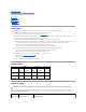
Back to Contents Page Advanced Troubleshooting Dell™ Dimension™ 3000 Systems Service Manual Power Lights Network Lights Diagnostic Lights Beep Codes System Messages Power Lights The power button light located on the front of your computer illuminates and blinks or remains solid to indicate different states: l If the power light is green, the power status is good and the computer is functioning properly. l If the power light is green and the computer is not responding, see Network Lights.
The computer is in a normal off condition or a possible pre-BIOS failure has occurred. Plug the computer into a working electrical outlet and press the power button. Memory modules are detected, but a memory failure has occurred. l l l l A possible graphics card failure has occurred. l l l If you have one memory module installed, reinstall the memory module and restart the computer.
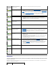
Code Cause 1-3-1 through 2-4-4 Memory not being properly identified or used 4-3-1 Memory failure above address 0FFFFh If you hear one of the following beep codes, see "Contacting Dell" in your Owner's Manual for instructions on obtaining technical assistance.
CMOS System Options Not Set CMOS Display Type Mismatch CMOS Memory Size Mismatch CMOS Time and Date Not Set Diskette Boot Failure Drive A or B is present but has failed the BIOS POST. Ensure that the drive is installed correctly in the computer and defined correctly in the system setup program. Check the interface cable at both ends. DMA Error Error in the DMA controller on the system board. The keyboard or system board may need to be replaced.
Back to Contents Page Before You Begin Dell™ Dimension™ 3000 Systems Service Manual Getting Started Recommended Tools Turning Off Your Computer Before Working Inside Your Computer Getting Started This chapter provides procedures for removing and installing the components in your computer. Unless otherwise noted, each procedure assumes that the following conditions exist: l You have performed the steps in Turning Off Your Computer and Before Working Inside Your Computer.
2. Disconnect any telephone or telecommunication lines from the computer. 3. Disconnect your computer and all attached devices from their electrical outlets, and then press the power button to ground the system board. CAUTION: To guard against electrical shock, always unplug your computer from the electrical outlet before opening the cover. 4. Open the computer cover.
Back to Contents Page Replacing the Computer Cover Dell™ Dimension™ 3000 Systems Service Manual CAUTION: Before you begin any of the procedures in this section, follow the safety instructions located in the Product Information Guide. 1. Ensure that all cables are connected, and fold cables out of the way. Gently pull the power cables toward you so that they do not get caught underneath the drives. 2. Ensure that no tools or extra parts are left inside the computer. 3.
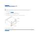
Back to Contents Page Removing the Computer Cover Dell™ Dimension™ 3000 Systems Service Manual CAUTION: Before you begin any of the procedures in this section, follow the safety instructions located in the Product Information Guide. CAUTION: To guard against electrical shock, always unplug your computer from the electrical outlet before opening the cover. 1. Follow the procedures in Before You Begin. 2. Lay your computer on its side with the computer cover facing up. 3.
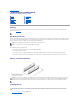
Back to Contents Page Removing and Installing Parts Dell™ Dimension™ 3000 Systems Service Manual Memory CD/DVD Drive Cards Processor Front Panel Fan Assembly Drives System Board Hard Drive Power Supply Floppy Drive Battery Memory You can increase your computer memory by installing memory modules on the system board. For information on the type of memory supported by your computer, see Specifications.
2. Ensure that your computer and attached devices are turned off. If your computer and attached devices did not automatically turn off when you shut down your computer, turn them off now. NOTICE: To disconnect a network cable, first unplug the cable from your computer and then unplug it from the network wall jack. 3. Disconnect any telephone or telecommunication lines from the computer. 4.
NOTICE: To connect a network cable, first plug the cable into the network wall jack and then plug it into the computer. 12. Connect your computer and devices to electrical outlets, and then turn them on. 13. Click the Start button, right-click My Computer, and then click Properties. 14. Click the General tab. 15. To verify that the memory is installed correctly, check the amount of memory (RAM) listed.
Ensure that the card is fully seated and that its bracket is within the card slot. 4. Secure the card bracket with the screw you removed in step 2. 5. Connect any cables that should be attached to the card. For information about the card's cable connections, see the documentation for the card. NOTICE: Do not route card cables over or behind the cards. Cables routed over the cards can cause damage to the equipment. 6. 7. 8. If you installed a sound card: a.
If you need a filler bracket, see "Contacting Dell" in your Owner's Manual for instructions on obtaining technical assistance. NOTE: Installing filler brackets over empty card-slot openings is necessary to maintain FCC certification of the computer. The brackets also keep dust and dirt out of your computer. NOTICE: To connect a network cable, first plug the cable into the network wall jack and then plug it into the computer. 6.
1. Press in the two insert tabs. 2. Push out the front-panel insert. Reattaching the Front Panel 1. Reattach the front panel to the side hinges. 2. Rotate the front panel until it snaps onto the front of the computer. Drives Your computer supports a combination of these devices: l Up to two hard drives l One optional floppy l Up to two CD or DVD drives General Installation Guidelines Connect IDE hard drives to the system board connector labeled PRI IDE.
Connecting Drive Cables When you install a drive, you connect two cables—a DC power cable and a data cable—to the back of the drive and to the system board. Some drives may also have an audio connector; one end of the audio cable will attach to the drive connector and the other will attach to the system board. Drive Interface Connectors Most interface connectors are keyed for correct insertion; that is, a notch or a missing pin on one connector matches a tab or a filled-in hole on the other connector.
b. 3. Remove the bracket for the hard drive from the computer. If you are replacing the hard drive, remove the drive from the bracket: a. Remove the hard drive-securing screws. b. Remove the hard drive from the bracket. Installing a Hard Drive 1. Unpack the replacement hard drive, and prepare it for installation. 2. Check the documentation for the drive to verify that it is configured for your computer. 3. Remove the hard drive bracket. 4.
8. Close the computer cover. NOTICE: To connect a network cable, first plug the cable into the network wall jack and then plug it into the computer. 9. Connect your computer and devices to electrical outlets, and turn them on. See the documentation that came with the drive for instructions on installing any software required for drive operation. 10. If the drive you just installed is the primary drive, insert a bootable floppy disk into drive A. 11. Turn on the computer. 12.
3. Remove the floppy drive from the bracket: a. Remove all four drive-securing screws (two on each side). b. Remove the floppy drive from the bracket. Installing a Floppy Drive 1. Remove the floppy drive bracket from the computer. 2. If you are replacing a floppy drive, remove the drive from the bracket. 3. Attach the floppy drive bracket to the floppy drive: 4. a. Align the screw holes on the drive with the screw holes on the bracket. b.
NOTICE: To connect a network cable, first plug the cable in to the network wall jack and then plug it in to the computer. 10. Connect your computer and devices to their electrical outlets, and turn them on. See the documentation that came with the drive for instructions on installing any software required for drive operation. 11. Enter system setup and update the appropriate Diskette Drive option. 12. Verify that your computer works correctly by running the Dell Diagnostics.
Installing a CD/DVD Drive 1. If you are installing a new drive, unpack the drive and prepare it for installation. Check the documentation that accompanied the drive to verify that the drive is configured for your computer. If you are installing an IDE drive, configure the drive for the cable select setting. 2. If you are replacing a drive, remove the existing drive. 3. Gently slide the drive into place in the drive bay. 4.
4. After the drive is in place, apply pressure to ensure that the drive is fully seated. 5. Use the securing screw that came with the drive to attach the drive to the computer. NOTICE: Match the colored strip on the cable with pin 1 on the drive (pin 1 is marked as "1"). 6. Connect the power cable to the system board. 7. Locate the data cable from the CD or DVD drive in the upper drive bay and connect its middle data connector to the new drive. 8. Reattach the front panel. 9.
CAUTION: Before you begin any of the procedures in this section, follow the safety instructions located in the Product Information Guide. 1. Follow the procedures in Before You Begin. 2. Disconnect the cooling fan power cable from the fan connector on the system board. 3. Disconnect the power cable from the processor power connector on the system board. 4. Lift up the airflow shroud. CAUTION: The heat sink can get very hot during normal operation.
8. To remove the processor from the socket, lift the processor vertically in one motion. Leave the release lever extended in the release position so that the socket is ready for the new processor. Installing the Processor NOTICE: Ground yourself by touching an unpainted metal surface on the back of the computer. 1. Unpack the new processor. NOTICE: You must position the processor correctly in the socket to avoid permanent damage to the processor and the computer when you turn on the computer. 2.
a. Slide one end of the heat sink under the retention tab. b. Lower the heat sink until it fits securely in the module. NOTICE: Ensure the heat sink is correctly seated and secure. 8. Lower the airflow shroud over the heat sink. 9. Reconnect the cooling fan power cable to the fan connector on the system board. 10. Reconnect the power cable to the processor power connector on the system board. 11. Close the computer cover.
5. Disconnect the fan power cable from its connector on the system board. 6. Pull the fan release lever away from the back of the computer and slide the fan toward the release lever. 7. Remove the fan assembly from the computer. Replacing the Fan Assembly 1. Align the fan assembly tabs with the holes in the back of the computer. 2. Slide the fan assembly away from the fan release lever until it clicks in place. 3. Reconnect the DC power cables to the drives and system board. 4.
CAUTION: Before you begin any of the procedures in this section, follow the safety instructions in the Product Information Guide. CAUTION: To guard against electrical shock, always unplug your computer from the electrical outlet before removing the cover. 1. Follow the procedures in Before You Begin. 2. Remove the floppy drive. 3. Remove any cards that are installed. 4. Disconnect all cables from the system board. 5. Lift up the heat-sink shroud.
step 8 of the preceding procedure. 4. Reinstall the fan assembly. 5. Reinstall the microprocessor heat sink, and then lower the heat-sink shroud. 6. Reattach the cables to the system board. 7. Reinstall any cards. 8. Replace the floppy drive. 9. Replace the computer cover. NOTICE: To connect a network cable, first plug the cable into the network wall jack and then plug it into the computer. 10. Connect your computer and devices to electrical outlets, and turn them on.
1. Slide the power supply into place. 2. Replace the four screws that secure the power supply to the back of the computer. 3. Reinstall the fan assembly. 4. Reconnect the DC power cables to the drives and system board. 5. Replace the computer cover. 6. Connect the AC power cable to the AC power connector on the back of the power supply. NOTICE: To connect a network cable, first plug the cable into the network wall jack and then plug it into the computer. 7.
7. Connect your computer and devices to electrical outlets, and turn them on. 8. Enter system setup and restore the settings you recorded in step 1. 9. Properly dispose of the old battery (see the "Battery Disposal" section of your Product Information Guide).
Back to Contents Page Technical Specifications Dell™ Dimension™ 3000 Systems Service Manual Processor Drives Memory Connectors Computer Information Controls and Lights Video Power Audio Physical Expansion Bus Environmental Processor Processor type l Intel® Pentium® 4 processor that runs at 2.8 GHz , 3.0 GHz, and 3.2 GHZ internally and 800 MHz externally with Hyper-Threading Technology l Intel Pentium 4 processor that runs at 2.
Expansion Bus Bus type PCI Bus speed 33 MHz PCI connectors three connector size 120 pins connector data width (maximum) 32 bits Drives Externally accessible: Available devices one bay for a floppy drive, and two bays for CD/DVD drive floppy drive, USB memory devices, CD drive, CD-RW drive, DVD drive, DVD-RW drive, and DVD and CD-RW combo drive Internally accessible: one bay for 1-inch-high IDE hard drives Connectors External connectors: Serial 9-pin connector; 16550C-compatible Para
Operating 10º to 35ºC (50º to 95ºF) NOTE: At 35°C (95°F), the maximum operating altitude is 914 m (3000 ft). Storage Relative humidity –40º to 65ºC (–40º to 149ºF) 20% to 80% (noncondensing) Maximum vibration: Operating 0.25 G at 3 to 200 Hz at 0.5 octave/min Storage 2.20 Grms at 10 to 500 Hz at 1 octave/min Maximum shock: Operating 105 G, 2 ms Storage 32 G with a velocity change of 596.9 cm/sec (235 inches/sec) Altitude: Operating –15.
Back to Contents Page System Setup Dell™ Dimension™ 3000 Systems Service Manual Overview Entering System Setup System Setup Screens System Setup Options Boot Sequence Clearing Forgotten Passwords Overview Use system setup as follows: l To change the system configuration information after you add, change, or remove any hardware in your computer l To set or change a user-selectable option such as the user password l To read the current amount of memory or set the type of hard drive in
NOTE: If you insert a boot device and restart the computer, this option appears in the system setup menu. To boot from a USB memory device, select the USB device and move it so it becomes the first device in the list. Drives Diskette Drive Identifies and defines the floppy drive attached to the FLOPPY connector on the system board as Off, USB, Internal, or Read Only. Drives 0 through 3 Identifies the drives attached to the PRI IDE connectors on the system board, and lists the capacity for hard drives.
Maintenance CMOS Defaults Restores the computer's factory-installed default settings. Event Log Displays the system event log. BIOS Update After downloading a new version of the BIOS, use this option to identify and define the location of the BIOS update file. The options are Diskette or Disk. POST Behavior Fastboot When set to On (default), your computer starts more quickly because it skips certain configurations and tests.
3. Press the up- and down-arrow keys to move through the list of devices. 4. Press the spacebar to enable or disable a device (enabled devices have a check mark). 5. Press plus (+) or minus (–) to move a selected device up or down the list. Clearing Forgotten Passwords CAUTION: Before you begin any of the procedures in this section, follow the safety instructions located in the Product Information Guide. 1. Follow the procedures in Before You Begin. 2.
Back to Contents Page Technical Overview Dell™ Dimension™ 3000 Systems Service Manual Inside View of Your Computer System Board Components Power Supply DC Connector Pin Assignments Inside View of Your Computer CAUTION: Before you begin any of the procedures in this section, see the safety instructions located in the Product Information Guide. CAUTION: To guard against electrical shock, always unplug your computer from the electrical outlet before opening the computer cover.
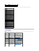
Power Supply DC Connector Pin Assignments The 250-W power supply can operate from an AC power source of 115 VAC or 230 VAC at 50 – 60 Hz. The power supply provides the DC operating voltages and currents listed in the following table. 1 2 Output Voltage Minimum Current (A) Maximum Current (A) +12 VDC 0.0 16.03 +5 VDC 1.0/0.2 4 22.0 +3.3 VDC 0.1/0.05 18.0 - - - –12 VDC 0.0 1.0 +5 VFP 0.0 2.
Pin Number Signal name Wire Color 1 +3.3 VDC Orange 2 +3.3 VDC Orange 3 COM Black 4 +5 VDC Red 5 COM Black 6 +5 VDC Red 7 COM Black 8 POK Gray 9 +5 VFP Purple 10 +12 VDC Yellow 11 +3.
Pin Number Signal Name 18-AWG Wire Color 1 - No connect 2 COM Black 3 COM Black 4 +3.
Back to Contents Page Dell™ Dimension™ 3000 Systems Service Manual NOTE: A NOTE indicates important information that helps you make better use of your computer. NOTICE: A NOTICE indicates either potential damage to hardware or loss of data and tells you how to avoid the problem. CAUTION: A CAUTION indicates a potential for property damage, personal injury, or death. For a complete list of abbreviations and acronyms, see the Dell Dimension Help file.