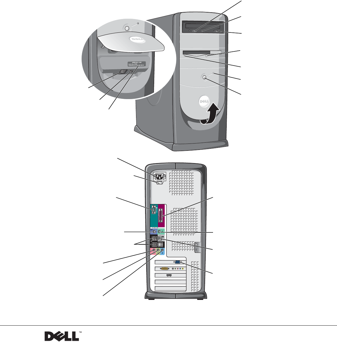
Dell™ Dimension™ 8250 Series CD or DVD volume control dial CD or DVD activity light CD or DVD drive eject button floppy drive eject button* floppy drive light* hard drive light USB 2.0 connectors (2) power button headphone connector service tag *On computers with an optional floppy drive. power connector voltage selection switch serial connector parallel connector keyboard connector mouse connector USB 2.
Hints, Notices, and Cautions HINT: A HINT indicates important information that helps you make better use of your computer. NOTICE: A NOTICE indicates either potential damage to hardware or loss of data and tells you how to avoid the problem. CAUTION: A CAUTION indicates a potential for property damage, personal injury, or death. Abbreviations and Acronyms For a complete list of abbreviations and acronyms, see the Tell Me How help file. To access help files, see page 38.
Contents CAUTION: Safety Instructions General . . . . . . . . . . . . . . . . . . . 9 . . . . . . . . . . . . . . . . . . . . . . . . . . . . . 9 When Using Your Computer . . . . . . . . . . . . . . . . . . . . When Working Inside Your Computer . . . . . . . . . . . . . Protecting Against Electrostatic Discharge 12 . . . . . . . . . . . 13 . . . . . . . . . . . . . . . . . 13 . . . . . . . . . . . . . . . . . . . . . . . .
Copying CDs . . . . . . . . . . . . . . . . . . . . . . . . . . . . Using Easy CD Creator Basic . . . . . . . . . . . . . . . . . Using Blank CD-R Discs or Blank CD-RW Discs Helpful Tips 31 . . . . . . . . 31 . . . . . . . . . . . . . . . . . . . . . . . . . . 31 How to Copy a CD Hyper-Threading 30 . . . . . . . . . . . . . . . . . . . . . . . 32 . . . . . . . . . . . . . . . . . . . . . . . . . . 33 Turning Off the Computer . . . . . . . . . . . . . . . . . . . . . 34 . . . . . . . . . .
IEEE 1394 Device Problems . . . . . . . . . . . . . . . . . . . . 47 . . . . . . . . . . . . . . . . . . . . . . . . . 48 . . . . . . . . . . . . . . . . . . . . . . . . . . 49 Keyboard Problems Mouse Problems . . . . . . . . . . . . . . . . . . . . . . . . . 50 Power Problems . . . . . . . . . . . . . . . . . . . . . . . . . . . 51 Printer Problems . . . . . . . . . . . . . . . . . . . . . . . . . . 53 . . . . . . . . . . . . . . . . . . . . . . . . .
Resolving Software and Hardware Incompatibilities . . . . . . . 70 . . . . . . . . . . . . . . 71 . . . . . . . . . . . . . . . . . . . . . . 71 Reinstalling Microsoft® Windows® XP Before You Reinstall Reinstalling Windows XP . . . . . . . . . . . . . . . . . . . Reinstalling Drivers and Software . . . . . . . . . . . . . . . 71 74 4 Adding Parts Front and Back View of the Computer . . . . . . . . . . . . . . 76 . . . . . . . . . . . . . . . . . . . . . . . . . . 76 . . . . . . . . . . . .
Adding a Floppy Drive . . . . . . . . . . . . . . . . . . . . . . 103 . . . . . . . . . . . . . . . 103 . . . . . . . . . . . . . . . . . . . 105 . . . . . . . . . . . . . . . . . . . 107 . . . . . . . . . . . . . . . . . . . . . . . . . . 110 Removing the Front-Panel Insert Installing a Floppy Drive Closing the Computer Cover 5 Appendix Specifications . Standard Settings . . . . . . . . . . . . . . . . . . . . . . . . Viewing Settings . . . . . . . . . . . . . . . . . . . . . . .
One-Year End-User Manufacturer Guarantee (Latin America and the Caribbean Only) . . . . . . . . . . . . Intel® Warranty Statement for Pentium® and Celeron® Processors Only (U.S. and Canada Only) Index 8 Contents . . . . . . . . . . . . . . . . . . . . . . . . . . . . . . . . . . . . . . . . .
CAUTION: Safety Instructions Use the following safety guidelines to help ensure your own personal safety and to help protect your computer and working environment from potential damage. General • Do not attempt to service the computer yourself unless you are a trained service technician. Always follow installation instructions closely. • To help prevent electric shock, plug the computer and device power cables into properly grounded electrical outlets.
w w w. d e l l . c o m | s u p p o r t . d e l l . c o m CAUTION: Safety Instructions (continued) 10 • To avoid shorting out your computer when disconnecting a network cable, first unplug the cable from the network adapter on the back of your computer, and then from the network jack. When reconnecting a network cable to your computer, first plug the cable into the network jack, and then into the network adapter.
When Using Your Computer As you use your computer, observe the following safe-handling guidelines. CAUTION: Do not operate your computer with any cover(s) (including computer covers, bezels, filler brackets, front-panel inserts, and so on) removed.
w w w. d e l l . c o m | s u p p o r t . d e l l . c o m When Using Your Computer (continued) When Working Inside Your Computer Before you open the computer cover, perform the following steps in the sequence indicated. CAUTION: Do not attempt to service the computer yourself, except as explained in your online Dell™ documentation or in instructions otherwise provided to you by Dell. Always follow installation and service instructions closely.
When Using Your Computer (continued) • Handle components and cards with care. Do not touch the components or contacts on a card. Hold a card by its edges or by its metal mounting bracket. Hold a component such as a microprocessor chip by its edges, not by its pins. CAUTION: There is a danger of a new battery exploding if it is incorrectly installed. Replace the battery only with the same or equivalent type recommended by the manufacturer. Do not dispose of the battery along with household waste.
w w w. d e l l . c o m | s u p p o r t . d e l l . c o m When Using Your Computer (continued) Battery Disposal Your computer uses a lithium coin-cell battery. The lithium coin-cell battery is a long-life battery, and it is very possible that you will never need to replace it. However, should you need to replace it, see page 117. Do not dispose of the battery along with household waste. Contact your local waste disposal agency for the address of the nearest battery deposit site.
Finding Information for Your Computer What Are You Looking For? Find it Here • • • • ResourceCD A diagnostic program for my computer Drivers for my computer My computer documentation My device documentation You can use this CD to access documentation or reinstall drivers (see page 66) • • • • How to set up a printer How to troubleshoot and solve problems How to add parts How to contact Dell • Express Service Code and Service Tag Number • Microsoft® Windows® License Label Owner’s Manual Express Ser
w w w. d e l l . c o m | s u p p o r t . d e l l . c o m What Are You Looking For? Find it Here • How to reinstall my operating system Operating System CD If you reinstall your operating system, use the ResourceCD to reinstall drivers for the devices that came with your computer.
What Are You Looking For? Find it Here • How to set up my computer Setup diagram • Tips on using Windows • How to clean my computer • How to use my mouse and keyboard Te l l M e H o w h e l p f i l e 1 Click the Start button, and then click Help and Support. 2 Click User and system guides, and then click User’s guides. 3 Click Tell Me How. • How to use Windows XP • Documentation for my computer and devices Windows XP Help and Support Center 1 Click the Start button, and then click Help and Support.
w w w. d e l l . c o m | s u p p o r t . d e l l .
1 SECTION 1 Setting Up and Using Yo u r C o m p u t e r Setting Up a Printer Connecting Two Monitors Transferring Information to a New Computer Setting Up a Home and Office Network Connecting to the Internet Copying CDs Hyper-Threading Turning Off the Computer
w w w. d e l l . c o m | s u p p o r t . d e l l . c o m Setting Up a Printer NOTICE: Complete the operating system setup before you connect a printer to the computer.
parallel connector on computer connector on printer screws (2) clips (2) parallel printer cable notches (2) 4 Turn on the printer and then turn on the computer. If the Add New Hardware Wizard window appears, click Cancel. 5 Install the printer driver if necessary. See the documentation that came with your printer. Connecting a USB Printer 1 Complete the operating system setup if you have not already done so. 2 Install the printer driver if necessary.
w w w. d e l l . c o m | s u p p o r t . d e l l . c o m USB connector on computer USB printer cable USB connector on printer Connecting Two Monitors If you purchased a video card that supports dual monitors, follow the instructions in this section to connect and enable your monitors. Connecting the Monitors to Your Computer HINT: If both monitors have VGA connectors, you must have the optional VGA adapter. 22 1 Save any open files, close any open programs, and shut down the computer.
optional VGA adapter If one monitor has a VGA connector and the other one has a DVI connector: a Connect the VGA connector on the monitor to the VGA (blue) connector on the computer. b Connect the DVI connector on the other monitor to the DVI (white) connector on the computer. HINT: If you are connecting two flat panel monitors, at least one of them must have a VGA connector.
w w w. d e l l . c o m | s u p p o r t . d e l l . c o m 3 Restart the computer. The Microsoft® Windows® desktop displays on the primary monitor. 4 Use the instructions in the following sections to enable clone mode or extended desktop mode in the display settings. For more information on changing display settings, see the Help and Support Center (click the Start button and click Help and Support). Enabling Clone Mode In clone mode, both monitors display the same image.
4 Click OK to continue. The screen temporarily blacks out, and then the same image displays on both monitors. 5 Click Yes to accept the changes. Enabling Extended Desktop Mode In extended desktop mode, you can drag objects from one screen to the other, effectively doubling the amount of viewable work space. 1 Right-click an empty spot on the desktop and click Properties. 2 Click the Settings tab. Two monitors are displayed on the Settings tab. 3 Click the grayed-out monitor icon.
w w w. d e l l . c o m | s u p p o r t . d e l l . c o m 3 On the Which computer is this? screen, click New Computer, and then click Next. 4 On the Do you have a Windows XP CD? screen, click I will use the wizard from the Windows XP CD, and then click Next. 5 When the Now go to your old computer screen appears, go to your old or source computer. Do not click Next at this time.
Setting Up a Home and Office Network Connecting to a Network Adapter Before you connect your computer to a network, the computer must have a network adapter installed and a network cable connected to it. To connect a network cable: 1 Connect the network cable to the network adapter connector on the back of your computer. 2 Connect the other end of the network cable to a network connection device, such as a network wall jack. HINT: Do not use a network cable with a telephone wall jack.
w w w. d e l l . c o m | s u p p o r t . d e l l . c o m HINT: Selecting the connection method This computer connects directly to the Internet enables the integrated firewall provided with Microsoft® Windows® XP operating system. HINT: ISPs may vary by country. 3 Click Checklist for creating a network. 4 Complete the checklist and required preparations, and return to the Network Setup Wizard. 5 Follow the instructions on the screen.
If you do not have an MSN Explorer or AOL icon on your desktop or if you want to set up an Internet connection with a different ISP: 1 Save and close any open files, and exit any open programs. 2 Click the Start button and click Internet Explorer. The New Connection Wizard appears. 3 Click Connect to the Internet. 4 In the next window, click the appropriate option: 5 • If you do not have an ISP and want to select one, click Choose from a list of Internet service providers (ISPs).
w w w. d e l l . c o m | s u p p o r t . d e l l . c o m Copying CDs HINT: Ensure that you follow all copyright laws when you create CDs. This section applies only to computers that have a CD- or DVD-recording device. The information in this section is based on the Roxio Easy CD Creator Basic documentation that came with your computer. See the following section, "Using Easy CD Creator Basic," for instructions on how to locate that documentation.
Using Easy CD Creator Basic See the Easy CD Creator Basic documentation for instructions on how to use the program, information about different recording techniques, and CD media limitations. The Easy CD Creator Basic documentation is located in the Microsoft® Windows® XP Help and Support Center (see "Finding Information for Your Computer" on page 15). The documentation is also provided on the Dell Dimension ResourceCD, which is included with your computer.
w w w. d e l l . c o m | s u p p o r t . d e l l . c o m • Do not burn a blank CD-R or CD-RW disc to its maximum capacity; for example, do not copy a 650-MB file to a 650-MB blank CD. The CD-RW drive needs 1 or 2 MB of the blank CD to finalize the recording. • Use a blank CD-RW disc to practice CD recording until you are familiar with CD recording techniques. If you make a mistake, you can erase the CD-RW disc and try again.
6 Insert a blank CD into the CD-RW drive and close the tray. The recording starts automatically. 7 After the recording completes, click OK. Hyper-Threading HINT: You must use CD-R discs to burn music CDs that you want to play in regular stereos. CD-RW discs do not play in most home or car stereos.
w w w. d e l l . c o m | s u p p o r t . d e l l . c o m Turning Off the Computer NOTICE: To avoid losing data, turn off your computer by performing a Microsoft® Windows® operating system shutdown, as described next, rather than by pressing the power button. HINT: If you are having difficulty turning off your computer, see "General Problems" on page 44. 1 Save and close any open files, exit any open programs, click the Start button, and then click Turn Off Computer.
2 SECTION 2 Solving Problems Finding Solutions Finding Help Information Battery Problems Drive Problems E-Mail, Modem, and Internet Problems Error Messages General Problems IEEE 1394 Device Problems Keyboard Problems Mouse Problems Network Problems Power Problems Printer Problems Scanner Problems Sound and Speaker Problems Video and Monitor Problems
w w w. d e l l . c o m | s u p p o r t . d e l l . c o m Finding Solutions Sometimes it’s difficult to figure out where to go for answers. Use this chart to help you quickly find the answers to your questions. See page 51. Press a key or move the mouse. See the Tell Me How help file for information on standby mode. Get technical assistance from Dell. See page 120. See page 43.
See page 56. See page 55. See page 53. See page 41. See page 49. See page 48. See page 39. See page 50. See page 54. See page 43. See page 44. See page 41. See page 41. See page 44.
w w w. d e l l . c o m | s u p p o r t . d e l l . c o m Finding Help Information TO A C C E S S T H E Tell Me How H E L P F I L E — 1 Click the Start button, and then click Help and Support. 2 Click User and system guides, and then click User’s guides. 3 Click Tell Me How. TO A C C E S S W I N D O W S H E L P — 1 Click the Start button, and then click Help and Support. 2 Type a word or phrase that describes your problem, and then click the arrow icon. 3 Click the topic that describes your problem.
Drive Problems Floppy drive problems E N S U R E T H A T W I N D O W S ® R E C O G N I Z E S T H E D R I V E — Click the Start button and click My Computer. If the floppy drive is not listed, perform a full scan with your antivirus software to check for and remove viruses. Viruses can sometimes prevent Windows from recognizing the drive. TE S T T H E D R I V E — • Insert another disk to eliminate the possibility that the original floppy disk is defective.
w w w. d e l l . c o m | s u p p o r t . d e l l . c o m CD drive problems HINT: High-speed CD drive vibration is normal and may cause noise. This does not indicate a defect in the drive or the CD. A D J U S T T H E W I N D O W S V O L U M E C O N T R O L — Click the speaker icon in the lower-right corner of your screen. • Ensure that the volume is turned up by clicking the slidebar and dragging it up. • Ensure that the sound is not muted by clicking any boxes that are checked.
DVD drive problems TE S T T H E D R I V E W I T H A N O T H E R DVD — Insert another DVD to eliminate the possibility that the original DVD is defective. E N S U R E T H A T W I N D O W S R E C O G N I Z E S T H E D R I V E — Click the Start button and click My Computer. If the DVD drive is not listed, perform a full scan with your antivirus software to check for and remove viruses. Viruses can sometimes prevent Windows from recognizing the drive.
w w w. d e l l . c o m | s u p p o r t . d e l l . c o m CONNECT THE MODEM DIRECTLY TO THE TELEPHONE WALL JACK — If you have other telephone devices sharing the line, such as an answering machine, fax machine, surge protector, or line splitter, then bypass them and use the telephone to connect the modem directly to the telephone wall jack. U S E A D I F F E R E N T T E L E P H O N E L I N E — If you are using a line that is 3 m (10 ft) or more in length, try a shorter one.
E N S U R E T H A T Y O U A R E C O N N E C T E D T O T H E I N T E R N E T — With the Outlook Express e-mail program open, click File. If Work Offline has a checkmark next to it, click the checkmark to remove it and connect to the Internet. ENSURE THAT YOU HAVE SUBSCRIBED TO AN INTERNET SERVICE P R O V I D E R — Contact an Internet service provider to subscribe. C O N T A C T Y O U R I N T E R N E T S E R V I C E P R O V I D E R — Contact your Internet service provider for assistance.
w w w. d e l l . c o m | s u p p o r t . d e l l . c o m NOT ENOUGH MEMORY OR RESOURCES. CLOSE SOME PROGRAMS AND T R Y A G A I N — You have too many programs open. Close all windows and open the program that you want to use. In some cases, you might have to restart your computer to restore computer resources. If so, try running the program that you want to use first. O P E R A T I N G S Y S T E M N O T F O U N D — Contact Dell (see page 120).
A program crashes repeatedly C H E C K T H E S O F T W A R E D O C U M E N T A T I O N — Many software manufacturers maintain websites with information that may help you solve the problem. Ensure that you properly installed and configured the program. If necessary, uninstall and then reinstall the program. HINT: Software usually includes installation instructions in its documentation or on a floppy disk or CD.
w w w. d e l l . c o m | s u p p o r t . d e l l . c o m ENSURE THAT YOU HAVE NOT MADE AN ERROR WHILE ENTERING D A T A — See the program documentation to make sure that the values or characters you are entering are valid. C H E C K F O R V I R U S E S — Use a virus-scanning program to check the hard drive, floppy disks, or CDs.
General hardware problems If your computer exhibits one or more of the following symptoms, a device conflict may exist: • Your computer locks up, particularly while using a specific device. • A recently added device does not work. • A sound card emits noise or demonstrates other problems. • Unintelligible characters print from the printer. • The mouse pointer does not move or "stutters" when it moves. • Messages appear stating that the computer is not operating at maximum performance.
w w w. d e l l . c o m | s u p p o r t . d e l l . c o m E N S U R E T H A T T H E I EEE 1394 D E V I C E I S R E C O G N I Z E D B Y WINDOWS® — 1 Click the Start button. 2 Click Control Panel. 3 Click Printers and Other Hardware. If your IEEE 1394 device is listed, Windows recognizes the device. I F Y O U H A V E P R O B L E M S W I T H A D E L L - P R O V I D E D I EEE 1394 D E V I C E — Contact Dell (see page 120).
TE S T T H E K E Y B O A R D — Connect a properly working keyboard to the computer, and try using the keyboard. If the new keyboard works, the original keyboard is faulty. C H E C K F O R I N T E R R U P T R E Q U E S T C O N F L I C T S — See page 70. Mouse Problems RE S T A R T T H E C O MP U T E R — 1 Simultaneously press to display the Start menu. 2 Type u, press the keyboard arrow keys to highlight Shut down or Turn Off, and then press .
w w w. d e l l . c o m | s u p p o r t . d e l l . c o m CHECK THE MOUSE CABLE — • Check the cable connector for bent or broken pins and for damaged or frayed cables. Straighten bent pins. • Ensure that the cable is firmly connected to the computer. TE S T T H E M O U S E — Connect a properly working mouse to the computer, and try using the mouse. If the new mouse works, the original mouse was faulty.
RE S T A R T T H E C O MP U T E R A ND T R Y T O L O G O N T O T H E N ET W OR K AGAIN C H E C K Y O U R N E T W O R K S E T T I N G S — Contact your network administrator or the person who set up your network to verify that your network settings are correct and that the network is functioning. C H E C K F O R I N T E R R U P T R E Q U E S T C O N F L I C T S — See page 70. Power Problems CAUTION: Before you begin any of the procedures in this section, follow the safety instructions on page page 9.
w w w. d e l l . c o m | s u p p o r t . d e l l . c o m I F T H E P O W E R L I G H T I S O F F — The computer is either turned off or is not receiving power. • Reseat the power cable into both the power connector on the back of the computer and the electrical outlet. • If the computer is plugged into a power strip, ensure that the power strip is plugged into an electrical outlet and that the power strip is turned on.
E L I M I N A T E I N T E R F E R E N C E — Electrical appliances on the same circuit or operating near the computer can cause interference. Other causes of interference are: • Power extension cables • Keyboard and mouse extension cables • Too many devices on a power strip • Multiple power strips connected to the same electrical outlet Printer Problems C H E C K T H E P R I N T E R D O C U M E N T A T I O N — See the printer documentation for setup and troubleshooting information.
w w w. d e l l . c o m | s u p p o r t . d e l l . c o m R E I N S T A L L T H E P R I N T E R D R I V E R — See the printer documentation for instructions. Scanner Problems HINT: Dell does not cover the scanner’s warranty. If you need technical assistance for your scanner, call the scanner’s manufacturer. See the scanner documentation for the correct phone number. C H E C K T H E S C A N N E R D O C U M E N T A T I O N — See the scanner documentation for setup and troubleshooting information.
Sound and Speaker Problems No sound from speakers C H E C K T H E S P E A K E R C A B L E C O N N E C T I O N S — Ensure that the speakers are connected as shown on the setup diagram supplied with the speakers. ENSURE THAT THE SUBWOOFER AND THE SPEAKERS ARE TURNED O N — See the setup diagram supplied with the speakers. If your speakers have volume controls, adjust the volume, bass, or treble to eliminate distortion. HINT: The volume control in some MP3 players overrides the Windows® volume setting.
w w w. d e l l . c o m | s u p p o r t . d e l l . c o m R U N T H E S P E A K E R D I A G N O S T I C S — Some speaker systems have selfdiagnostics. See the speaker documentation for diagnostics instructions. R E I N S T A L L T H E A U D I O ( S O U N D ) D R I V E R — See page 66. C H E C K F O R I N T E R R U P T R E Q U E S T C O N F L I C T S — See page 70.
C H E C K T H E M O N I T O R C A B L E C O N N E C T I O N — Check the connector for bent or broken pins. (It is normal for monitor cable connectors to have missing pins.)Ensure that the video cable is connected as shown on the setup diagram for your computer. TE S T T H E E L E C T R I C A L O U T L E T — Ensure that the electrical outlet is working by testing it with another device, such as a lamp.
w w w. d e l l . c o m | s u p p o r t . d e l l . c o m ADJUST THE WINDOWS® DISPLAY SETTINGS — 1 Click the Start button, and then click Control Panel. 2 Click Appearance and Themes. 3 Click Display, and then click the Settings tab. 4 Try different settings for Screen resolution and Color quality. R E S T O R E T H E R E C O M M E N D E D S E T T I N G S — Restore the original resolution and refresh rate settings. See the Tell Me How help file for instructions. To access help files, see page 38.
3 SECTION 3 Advanced Tr o u b l e s h o o t i n g Diagnostic Lights Dell Diagnostics Drivers Using System Restore Resolving Software and Hardware Incompatibilities Reinstalling Microsoft® Windows® XP
w w w. d e l l . c o m | s u p p o r t . d e l l . c o m Diagnostic Lights To help you troubleshoot a problem, your computer is equipped with four lights on the back panel labeled "A," "B," "C," and "D" (see page 78). These lights can be yellow or green. When the computer starts normally, the lights flash. After the computer starts, the lights remain green. If the computer malfunctions, the color and sequence of the lights identify the problem.
Diagnostic Code G Y G Y A B C D G G G Y A B C D Y G Y Y A B C D Definition Corrective Action Memory modules are detected, but a memory configuration or compatibility error exists. • Ensure that there are no special memory module/memory connector placement requirements (see page 93). • Verify that the memory modules that you are installing are compatible with the computer (see page 110). • If the problem persists, contact Dell (see page 120). Other failure.
w w w. d e l l . c o m | s u p p o r t . d e l l . c o m Diagnostic Code Y G Y G A B C D G Y Y Y A B C D Definition Corrective Action Video controller failure. • If the computer has a video card, remove the card and reinstall it (see page 98). • If the problem persists or the computer has integrated video, contact Dell (see page 120). No memory modules are detected. • Reinstall all memory modules (see page 93) and then restart the computer.
• Receive status messages that tell you whether tests completed successfully. • Receive error messages if problems are detected. Starting the Dell Diagnostics NOTICE: Only use the Dell Diagnostics to test your Dell™ computer. Using this program with other computers can result in error messages. Start the Dell Diagnostics from either your hard drive (see page 63) or from the Dell Dimension ResourceCD (see page 63). Starting the Dell Diagnostics From Your Hard Drive 1 Shut down and restart the computer.
w w w. d e l l . c o m | s u p p o r t . d e l l . c o m 7 Type 2 to start the Dell Diagnostics. 8 Select Run the 32 Bit Dell Diagnostics from the numbered list. If multiple versions are listed, select the version appropriate for your platform. 9 When the Dell Diagnostics Main Menu appears, select the test you want to run (see page 64). Dell Diagnostics Main Menu 1 HINT: The Service Tag number for your computer is located at the top of each test screen.
Tab Function Results Displays the results of the test and any error conditions encountered. Errors Displays error conditions encountered, error codes, and problem description. Help Describes the test and may indicate requirements for running the test. Configuration Displays your hardware configuration for the selected device.
w w w. d e l l . c o m | s u p p o r t . d e l l . c o m Many drivers such as the keyboard driver come with your Microsoft® Windows® operating system. You may need to install drivers if you: • Upgrade your operating system • Reinstall your operating system • Connect or install a new device If you experience a problem with any device, perform the steps in the following sections to identify whether the driver is the source of your problem and if necessary, to update the driver.
3 Click System. 4 In the System Properties screen, click the Hardware tab. 5 Click Device Manager. 6 Right-click the device for which the new driver was installed, and then click Properties. 7 Click the Drivers tab. 8 Click Roll Back Driver. If Device Driver Rollback does not resolve the problem, then use System Restore (see page 68) to return your computer to the operating state that existed before you installed the new driver.
w w w. d e l l . c o m | s u p p o r t . d e l l . c o m 5 HINT: The ResourceCD displays drivers only for hardware that came on your computer. If you installed additional hardware, the drivers for the new hardware might not be displayed by the ResourceCD. If those drivers are not displayed, exit the ResourceCD program. For drivers information, see the documentation that came with that product. At the Welcome Dell System Owner screen, click Next.
NOTICE: Before you restore the computer to an earlier operating state, save and close all open files and close all open programs. Do not alter, open, or delete any files or programs until the system restoration is complete. 1 Click the Start button, point to All Programs→ Accessories→ System Tools, and then click System Restore. 2 Ensure that Restore my computer to an earlier time is selected and click Next. 3 Click a calendar date to which you want to restore your computer.
w w w. d e l l . c o m | s u p p o r t . d e l l . c o m Enabling System Restore If you reinstall Windows XP with less than 200 MB of free hard-disk space available, System Restore is automatically disabled. To see if System Restore is enabled: 1 Click the Start button and click Control Panel. 2 Click Performance and Maintenance. 3 Click System. 4 Click the System Restore tab. 5 Make sure that Turn off System Restore is unchecked.
3 Click Hardware Troubleshooter in the Search Results list. 4 In the Hardware Troubleshooter list, click I need to resolve a hardware conflict on my computer, and click Next. Reinstalling Microsoft® Windows® XP Before You Reinstall If you are reinstalling the Windows XP operating system to correct a problem with a newly installed driver, use Windows XP Device Driver Rollback (see page 66) to replace the device driver with the previously installed version.
w w w. d e l l . c o m | s u p p o r t . d e l l . c o m 4 Press immediately after the DELL™ logo appears. If the operating system logo appears, wait until you see the Windows desktop, and then shut down the computer and try again. 5 Use the arrow keys to select CD-ROM, and then press . 6 Press any key when the Press any key to boot from CD message appears on the screen.
3 If you are reinstalling Windows XP Home Edition, at the What's your computer's name window, enter a name for your computer (or accept the name provided) and click Next. If you are reinstalling Windows XP Professional, at the Computer Name and Administrator Password window, enter a name for your computer (or accept the one provided) and a password, and then click Next. 4 If you have a modem installed, enter the requested information and click Next when the Modem Dialing Information screen appears.
w w w. d e l l . c o m | s u p p o r t . d e l l . c o m Reinstalling Drivers and Software 74 1 Reinstall the appropriate drivers (see page 66). 2 Reinstall your virus protection software. See the documentation that came with the software for instructions. 3 Reinstall your other software programs. See the documentation that came with the software for instructions.
4 SECTION 4 A d d i n g Pa r t s Front and Back View of the Computer Reattaching the Front Door and Hinge Arms Opening the Computer Cover Looking Inside Your Computer Installing and Removing Cards Adding Memory Adding or Replacing the AGP Card Adding a Second Hard Drive Adding a Floppy Drive Closing the Computer Cover
w w w. d e l l . c o m | s u p p o r t . d e l l . c o m Front and Back View of the Computer Front View 1 2 3 4* 5* 11 6 10 7 9 8 *On computers with an optional floppy drive.
1 CD or DVD volume control dial Move the dial to adjust the volume of your audio CD or DVD disc. 2 CD or DVD drive activity light The drive activity light is on when the computer reads data from the CD or DVD drive. 3 CD or DVD eject button Press this button to eject your CD from the CD or DVD drive. 4 floppy-drive eject button* Press this button to eject a floppy disk from the floppy drive.
w w w. d e l l . c o m | s u p p o r t . d e l l .
1 power connector The connection for the power cable. 2 voltage selection switch (may not be available on all computers) Set the switch for the voltage that most closely matches the AC power available in your location. See "When Using Your Computer" on page 11 for additional information. 3 parallel connector Connect a parallel device, such as a printer, to the parallel connector. If you have a USB printer, plug it into a USB connector.
w w w. d e l l . c o m | s u p p o r t . d e l l . c o m Reattaching the Front Door and Hinge Arms To prevent damage to your computer, the front-panel door is designed to "break away" if it is lifted up too far. If the front-panel door is open and it is pushed inward too hard, the hinge arms may also break away (the hinge arms are loose when they are detached).
front-panel insert use fingers to pull here 5 Lift both hinge arms to the horizontal position. 6 Use the two view slots to align the pivot bar with the two pivot-bar slots.
w w w. d e l l . c o m | s u p p o r t . d e l l . c o m view slots (2) pivot-bar slots (2) pivot bar hinge arms in horizontal position NOTICE: Before touching anything inside your computer, ground yourself by touching an unpainted metal surface, such as the metal at the back of the computer. While you work, periodically touch an unpainted metal surface to dissipate any static electricity that could harm internal components. 7 Pull the arms toward you until they snap into position.
Reattaching the Front Door CAUTION: Before you begin any of the procedures in this section, follow the safety instructions listed in "When Working Inside Your Computer" on page 12. 1 Shut down the computer through the Start menu (see page 33). 2 Disconnect the computer power cable from the electrical outlet. 3 Lower the hinge arms to the vertical position. 4 Align the two clips on the inside of the front door with the two hinge arms.
w w w. d e l l . c o m | s u p p o r t . d e l l . c o m Opening the Computer Cover CAUTION: Before you begin any of the procedures in this section, follow the steps listed in the safety instructions on page 12 CAUTION: To guard against electrical shock, always unplug your computer from the electrical outlet before opening the cover. 1 Shut down the computer (see page 33). NOTICE: To disconnect a network cable, first unplug the cable from your computer and then unplug it from the network wall jack.
release button arrow release button back of computer Looking Inside Your Computer CAUTION: Before you begin any of the procedures in this section, follow the safety instructions listed in "When Working Inside Your Computer" on page 12. NOTICE: Be careful when opening the computer cover to ensure that you do not inadvertently disconnect cables from the system board. HINT: The AGP card is removed from the following illustration to provide a better view of the inside of your computer.
w w w. d e l l . c o m | s u p p o r t . d e l l . c o m computer cover* (page 84 and page 107) drive cables power cables hard drive (page 100) power supply filler brackets for empty card slots (4) (page 88) system board (page 87) *Depending on the types of drives installed in your computer, the cover may not open as widely as shown in the figure.
System Board floppy drive connector (FLOPPY) main power connector (MAIN POWER) CD drive connector (SEC IDE) front panel switch connector (FNT PNL) hard drive connector (PRI IDE) battery socket (BATTERY) page 117 password jumper (PSWD) page 116 configuration jumper (CLR CM) memory module connectors (RIMM3, RIMM4) page 94 AGP slot connector (J6C1) microprocessor fan connector (FAN2) PCI card connectors (PCI1–PCI4) memory module connectors (RIMM1, RIMM2) page 94 microprocessor connector (J2E1) system
w w w. d e l l . c o m | s u p p o r t . d e l l . c o m Installing and Removing Cards CAUTION: Before you begin any of the procedures in this section, follow the steps in "When Working Inside Your Computer" on page 12. CAUTION: To guard against electrical shock, always unplug your computer from the electrical outlet before opening the cover. Your Dell™ computer provides slots for up to four 32-bit, 33-MHz cards. Cards If you are installing or replacing a card, follow the procedures in the next section.
card edge connector card connector filler bracket retention arm lever 7 If you are installing a new card, remove the filler bracket to create a card-slot opening. Then continue with step 9. 8 If you are replacing a card that is already installed in the computer, remove the card. If necessary, disconnect any cables connected to the card. Grasp the card by its top corners, and ease it out of its connector. 9 Prepare the card for installation.
w w w. d e l l . c o m | s u p p o r t . d e l l . c o m 10 Place the card in the connector and press down firmly. Ensure that the card is fully seated in the slot. If the card is full-length, insert the end of the card into the card guide bracket as you lower the card toward its connector on the system board. Insert the card firmly into the card connector on the system board.
retention arm alignment guide alignment bar filler bracket NOTICE: Do not route card cables over or behind the cards. Cables routed over the cards can prevent the computer cover from closing properly or cause damage to the equipment. 12 Connect any cables that should be attached to the card. See the documentation for the card for information about the card’s cable connections. NOTICE: To connect a network cable, first plug the cable into the network wall jack and then plug it into the computer.
w w w. d e l l . c o m | s u p p o r t . d e l l . c o m Removing a Card CAUTION: Before you begin any of the procedures in this section, follow the steps in "When Working Inside Your Computer" on page 12. 1 Shut down the computer (page 33). NOTICE: To disconnect a network cable, first unplug the cable from your computer and then unplug it from the network wall jack. 2 Turn off any attached devices and disconnect them from their electrical outlets.
Adding Memory CAUTION: Before you begin any of the procedures in this section, follow the steps in "When Working Inside Your Computer" on page 12. CAUTION: To guard against electrical shock, always unplug your computer from the electrical outlet before opening the cover. You can increase your computer memory by installing memory modules on the system board. For information on the type of memory supported by your computer, look under "Memory" in "Specifications" on page 110.
w w w. d e l l . c o m | s u p p o r t . d e l l . c o m Memory modules are the actual components that provide memory for the microprocessor; continuity modules are used only to complete the memory circuit if memory modules are not installed in all of the memory connectors. Another RDRAM requirement is that memory modules must be installed in pairs of matched memory size.
continuity modules in connectors RIMM3 and RIMM4 back of computer matched pair of memory modules in connectors RIMM1 and RIMM2 matched pair of memory modules in connectors RIMM3 and RIMM4 back of computer matched pair of memory modules in connectors RIMM1 and RIMM2 Removing a Memory Module 1 Shut down the computer (see page 33). NOTICE: To disconnect a network cable, first unplug the cable from your computer and then unplug it from the network wall jack.
w w w. d e l l . c o m | s u p p o r t . d e l l . c o m 4 Open the computer cover (see page 84). 5 Press out the securing clip at each end of the memory module connector. 6 Grasp the module and pull up. If the module is difficult to remove, gently ease the module back and forth to remove it from the connector. Adding a Memory Module 1 Shut down the computer (see page 33). NOTICE: To disconnect a network cable, first unplug the cable from your computer and then unplug it from the network wall jack.
securing clips (2) memory connectors on system board notches (2) memory module connector cutouts (2) step 5 step 6 step 7 6 Align the notches on the bottom of the module with the crossbar in the connector. NOTICE: To avoid damage to the memory module, press the module straight down into the socket with equal force applied at each end of the module. 7 Insert the module straight down into the connector, ensuring that it fits into the vertical guides at each end of the connector.
w w w. d e l l . c o m | s u p p o r t . d e l l . c o m 12 To verify that the memory is installed correctly, check the amount of memory (RAM) listed. Adding or Replacing the AGP Card CAUTION: Before you begin any of the procedures in this section, follow the steps in "When Working Inside Your Computer" on page 12. CAUTION: To guard against electrical shock, always unplug your computer from the electrical outlet before opening the cover. Your Dell™ computer provides a connector for an AGP card.
3 Pull the card up and out of the card clip. notch lever tab card clip AGP connector PCI connector back of computer Installing an AGP Card 1 To add or replace the card, press the card lever toward the PCI connector and gently press the card into the AGP connector until it clicks into place. AGP card card clip lever card clip slot connector 2 Release the card lever, ensuring that the tab fits into the notch on the front end of the card.
w w w. d e l l . c o m | s u p p o r t . d e l l . c o m 4 Close the computer cover (see page 107). 5 Connect the monitor cable to the card’s video connector. NOTICE: To connect a network cable, first plug the cable into the network wall jack and then plug it into the computer. 6 Connect your computer and devices to electrical outlets, and turn them on.
8 Remove the two green plastic rails from the inside of the hard-drive bay by gently pulling the rails up and out of the bay. 9 Attach the rails to the hard drive using the two screws attached to the rails. Ensure that the rail tabs are positioned at the back of the hard drive. NOTICE: Do not install any drive into the lower hard-drive bay until you have removed the green drive rails from the inside of the hard-drive bay.
w w w. d e l l . c o m | s u p p o r t . d e l l . c o m 12 Connect a power cable to the drive. NOTICE: Match the colored strip on the cable with pin 1 on the drive. 13 Locate the extra connector on the drive cable that is attached to your first hard drive and attach the connector to the second hard drive. Your computer uses cable-select drive cables.
16 See the documentation that came with the drive for instructions on installing any software required for drive operation. Adding a Floppy Drive CAUTION: Before you begin any of the procedures in this section, follow the safety instructions on page 9. CAUTION: To guard against electrical shock, always unplug your computer from the electrical outlet before opening the cover. 1 Perform an orderly computer shutdown using the operating system menu. 2 Turn off your computer and any devices.
w w w. d e l l . c o m | s u p p o r t . d e l l . c o m insert release tab floppy-drive bay 4 104 A d d i n g Pa r ts From outside the computer, pull the insert away from the computer’s front panel.
5 Remove the insert from the insert frame by pressing on the four tabs. insert frame for floppy-drive bay 6 Reattach the empty insert frame over the front of the drive bay. The insert frame fits only one way. Installing a Floppy Drive 1 Gently slide the drive into place until the tabs securely click into position. 2 Attach the floppy-drive cable to the floppy drive and to the system board floppy-drive connector.
w w w. d e l l . c o m | s u p p o r t . d e l l . c o m power cable floppy-drive cable cable restraint system board floppy-drive connector 4 Check all cable connections and fold cables out of the way to provide airflow for the fan and cooling vents. 5 Close the computer cover (see page 107). NOTICE: To connect a network cable, first plug the cable into the network wall jack and then plug it into the computer. 6 Connect your computer and devices to electrical outlets, and turn them on.
Closing the Computer Cover 1 Ensure that all cables are connected, and fold cables out of the way. Gently pull the power cables toward you so that they do not get caught underneath the drives. 2 Ensure that no tools or extra parts are left inside the computer. 3 Close the cover: a Pivot the cover down. b Press down on the right side of the cover until it closes. c Press down on the left side of the cover until it closes. d Ensure that both sides of the cover are locked. If not, repeat step 3.
A d d i n g Pa r ts w w w. d e l l . c o m | s u p p o r t . d e l l .
5 SECTION 5 Appendix Specifications Standard Settings Clearing Forgotten Passwords Replacing the Battery Dell Technical Support Policy (U.S.
w w w. d e l l . c o m | s u p p o r t . d e l l . c o m Specifications Microprocessor Microprocessor type Intel® Pentium® 4 L1 cache 8 KB L2 cache 512-KB pipelined-burst, eight-way set associative, write-back SRAM Memory Type PC800 or PC1066 RDRAM (non-ECC) Memory connectors four Memory capacities 64-, 128-, 256-, and 512-MB non-ECC Minimum memory 128 MB Maximum memory 2 GB for PC800 1.
Video Type AGP 4X, PCI Audio 1 Type Analog Devices AD1981a AC97 Codec Expansion Bus Bus types PCI and AGP Bus speed PCI: 33 MHz AGP: 66 MHz AGP connector one connector size 172 pins connector data width (maximum) 32 bits bus protocols 4x/2x modes at 1.5 V PCI connectors four connector size 120 pins connector data width (maximum) 32 bits Drives Externally accessible two 3.5-inch bays two 5.
w w w. d e l l . c o m | s u p p o r t . d e l l . c o m Connectors Externally accessible: Serial 9-pin connector; 16550C-compatible Parallel 25-hole connector (bidirectional) Video 15-hole connector Network Adapter RJ45 connector PS/2 (keyboard and mouse) 6-pin mini-DIN connector USB two front-panel and six back-panel USB 2.
Power DC power supply: Wattage 250 W Heat dissipation 853 BTU (fully-loaded computer without monitor) Voltage (see page 11 for important voltage setting information) 90 to 135 V at 50/60 Hz; 180 to 265 V at 50/60 Hz; 100 V at 50/60 Hz for Japanese computers Backup battery 3-V CR2032 lithium coin cell Physical Height 42.5cm (16.7 inches) Width 18.1 cm (7.13 inches) Depth 44.7 cm (17.6 inches) Weight 12.
w w w. d e l l . c o m | s u p p o r t . d e l l . c o m Environmental (continued) Altitude: Operating –15.2 to 3048 m (–50 to 10,000 ft)4 Storage –15.2 to 10,670 m (–50 to 35,000 ft) 4At 35°C (95°F), the maximum operating altitude is 914 m (3000 ft). Standard Settings The system setup program contains the standard settings for your computer. NOTICE: Unless you are an expert computer user, do not change the settings for this program. Certain changes might make your computer work incorrectly.
Viewing Settings 1 Turn on (or restart) your computer. 2 When the blue DELL™ logo appears, press immediately. If you wait too long and the operating system logo appears, continue to wait until you see the Microsoft® Windows® desktop. Then shut down your computer and try again.
w w w. d e l l . c o m | s u p p o r t . d e l l . c o m System Setup Screens The system setup program screens display the current configuration information for your computer. Information on the screen is divided into five areas: • Title — The area at the top of all system setup screens that displays your computer’s model number. • Computer data — Two boxes below the title that display the system processor, L2 cache, service tag, and the version number of the BIOS.
3 Disconnect the computer power cable from the wall outlet, and then press the power button to ground the system board. 4 Open the computer cover (see page 84). 5 Locate jumper PSWD on the system board (see page 87) and remove the jumper plug. 6 Close the computer cover (see page 107), plug your computer into an electrical outlet, and turn on the computer. The existing password(s) will be erased. 7 Shut down the computer (see page 33).
w w w. d e l l . c o m | s u p p o r t . d e l l . c o m CAUTION: A new battery can explode if it is incorrectly installed. Replace the battery only with the same or equivalent type recommended by the manufacturer. Discard used batteries according to the manufacturer’s instructions. 1 Record all the screens in system setup (see page 116) so that you can restore the correct settings in step 7. 2 Open the computer cover (see page 84). 3 Locate the battery socket labeled BATTERY (see page 118).
Dell Technical Support Policy (U.S. Only) Technician-assisted technical support requires the cooperation and participation of the customer in the troubleshooting process and provides for restoration of the operating system, application software, and hardware drivers to the original default configuration as shipped from Dell, as well as the verification of appropriate functionality of the computer and all Dellinstalled hardware.
w w w. d e l l . c o m | s u p p o r t . d e l l . c o m Definition of "Third-Party" Software and Peripherals Third-party software and peripherals include any peripheral, accessory, or application software sold by Dell not under the Dell brand (printers, scanners, cameras, games, and so on). Support for all third-party software and peripherals is provided by the original manufacturer of the product. Contacting Dell To contact Dell electronically, you can access the following websites: • www.dell.
Country (City) International Access Code Country Code City Code Department Name or Service Area, Website and E-Mail Address Aruba General Support Australia (Sydney) E-mail (Australia): au_tech_support@dell.com Area Codes, Local Numbers, and Toll-Free Numbers toll-free: 800-1578 International Access Code: 0011 E-mail (New Zealand): nz_tech_support@dell.
w w w. d e l l . c o m | s u p p o r t . d e l l . c o m Country (City) International Access Code Country Code City Code Department Name or Service Area, Website and E-Mail Address Belgium (Brussels) Website: support.euro.dell.com International Access Code: 00 E-mail: tech_be@dell.com Country Code: 32 E-mail for French Speaking Customers: support.euro.dell.
Country (City) International Access Code Country Code City Code Department Name or Service Area, Website and E-Mail Address Area Codes, Local Numbers, and Toll-Free Numbers Canada (North York, Ontario) Automated Order-Status System toll-free: 1-800-433-9014 International Access Code: 011 AutoTech (automated technical support) toll-free: 1-800-247-9362 TechFax toll-free: 1-800-950-1329 Customer Care (home/small business) toll-free: 1-800-847-4096 Customer Care (med.
w w w. d e l l . c o m | s u p p o r t . d e l l . c o m Country (City) International Access Code Country Code City Code Department Name or Service Area, Website and E-Mail Address China (Xiamen) Tech Support website: support.ap.dell.com/china Country Code: 86 Tech Support E-mail: cn_support@dell.
Department Name or Service Area, Website and E-Mail Address Country (City) International Access Code Country Code City Code Denmark (Copenhagen) Website: support.euro.dell.com International Access Code: 00 E-mail Support (portable computers): den_nbk_support@dell.com Country Code: 45 Area Codes, Local Numbers, and Toll-Free Numbers E-mail Support (desktop computers): den_support@dell.com E-mail Support (servers): Nordic_server_support@dell.
w w w. d e l l . c o m | s u p p o r t . d e l l . c o m Country (City) International Access Code Country Code City Code Department Name or Service Area, Website and E-Mail Address Area Codes, Local Numbers, and Toll-Free Numbers France (Paris) (Montpellier) Website: support.euro.dell.com International Access Code: 00 E-mail: support.euro.dell.
Country (City) International Access Code Country Code City Code Department Name or Service Area, Website and E-Mail Address Area Codes, Local Numbers, and Toll-Free Numbers Hong Kong Technical Support (Dimension™ and Inspiron™) 296 93188 International Access Code: 001 Technical Support (OptiPlex™, Latitude™, and Dell Precision™) 296 93191 Country Code: 852 India Customer Service (non-technical, post-sales issues) 800 93 8291 Transaction Sales toll-free: 800 96 4109 Large Corporate Accounts HK
w w w. d e l l . c o m | s u p p o r t . d e l l . c o m Country (City) International Access Code Country Code City Code Department Name or Service Area, Website and E-Mail Address Area Codes, Local Numbers, and Toll-Free Numbers Italy (Milan) Website: support.euro.dell.com International Access Code: 00 E-mail: support.euro.dell.
Country (City) International Access Code Country Code City Code Department Name or Service Area, Website and E-Mail Address Japan (Kawasaki) Website: support.jp.dell.
w w w. d e l l . c o m | s u p p o r t . d e l l . c o m Country (City) International Access Code Country Code City Code Latin America Department Name or Service Area, Website and E-Mail Address Area Codes, Local Numbers, and Toll-Free Numbers Customer Technical Support (Austin, Texas, U.S.A.) 512 728-4093 Customer Service (Austin, Texas, U.S.A.) 512 728-3619 Fax (Technical Support and Customer Service) (Austin, Texas, U.S.A.) 512 728-3883 Sales (Austin, Texas, U.S.A.
Country (City) International Access Code Country Code City Code Mexico Department Name or Service Area, Website and E-Mail Address Customer Technical Support International Access Code: 00 Country Code: 52 Area Codes, Local Numbers, and Toll-Free Numbers 001-877-384-8979 or 001-877-269-3383 Sales 50-81-8800 or 01-800-888-3355 Customer Service 001-877-384-8979 or 001-877-269-3383 Main 50-81-8800 or 01-800-888-3355 Montserrat General Support toll-free: 1-866-278-6822 Netherlands Antilles General
w w w. d e l l . c o m | s u p p o r t . d e l l . c o m Country (City) International Access Code Country Code City Code Department Name or Service Area, Website and E-Mail Address Area Codes, Local Numbers, and Toll-Free Numbers New Zealand E-mail (New Zealand): nz_tech_support@dell.com International Access Code: 00 E-mail (Australia): au_tech_support@dell.
Country (City) International Access Code Country Code City Code Department Name or Service Area, Website and E-Mail Address Portugal E-mail: support.euro.dell.com/es/es/emaildell/ International Access Code: 00 Technical Support Country Code: 35 Customer Care Sales Fax Area Codes, Local Numbers, and Toll-Free Numbers 800 834 077 800 300 415 or 800 834 075 800 300 410 or 800 300 411 or 800 300 412 or 121 422 07 10 121 424 01 12 Puerto Rico General Support 1-800-805-7545 St.
w w w. d e l l . c o m | s u p p o r t . d e l l . c o m Country (City) International Access Code Country Code City Code Department Name or Service Area, Website and E-Mail Address Area Codes, Local Numbers, and Toll-Free Numbers Spain (Madrid) Website: support.euro.dell.com International Access Code: 00 E-mail: support.euro.dell.
Country (City) International Access Code Country Code City Code Department Name or Service Area, Website and E-Mail Address Switzerland (Geneva) Website: support.euro.dell.com International Access Code: 00 E-mail: swisstech@dell.com Country Code: 41 E-mail for French-speaking HSB and Corporate Customers: support.euro.dell.
w w w. d e l l . c o m | s u p p o r t . d e l l . c o m Country (City) International Access Code Country Code City Code Department Name or Service Area, Website and E-Mail Address U.K. (Bracknell) Website: support.euro.dell.com International Access Code: 00 Customer Care website: dell.co.uk/lca/customerservices Country Code: 44 City Code: 1344 Area Codes, Local Numbers, and Toll-Free Numbers E-mail: dell_direct_support@dell.
Country (City) International Access Code Country Code City Code Department Name or Service Area, Website and E-Mail Address Area Codes, Local Numbers, and Toll-Free Numbers U.S.A.
w w w. d e l l . c o m | s u p p o r t . d e l l . c o m Regulatory Information Electromagnetic Interference (EMI) is any signal or emission, radiated in free space or conducted along power or signal leads, that endangers the functioning of a radio navigation or other safety service or seriously degrades, obstructs, or repeatedly interrupts a licensed radio communications service.
For additional regulatory information, see the Tell Me How help file that accompanied your computer. To access the help file, see page 38. NOM Information (Mexico Only) The following information is provided on the device(s) described in this document in compliance with the requirements of the official Mexican standards (NOM): Exporter: Dell One Dell Way Round Rock, TX 78682 Importer: Dell Computer de México, S.A. de C.V. Paseo de la Reforma 2620 - 11° Piso Col. Lomas Altas 11950 México, D.F.
Appendix w w w. d e l l . c o m | s u p p o r t . d e l l .
Limited Warranties and Return Policy Dell-branded hardware products purchased in the U.S. or Canada come with either a 90-day (U.S. only), one-year, two-year, three-year, or four-year limited warranty. To determine which warranty you purchased, see the invoice that accompanied your hardware product(s). The following sections describe the limited warranties and return policy for the U.S., the limited warranties and return policy for Canada, and the manufacturer guarantee for Latin America and the Caribbean.
w w w. d e l l . c o m | s u p p o r t . d e l l . c o m SOME STATES DO NOT ALLOW THE EXCLUSION OR LIMITATION OF INCIDENTAL OR CONSEQUENTIAL DAMAGES, SO THE ABOVE LIMITATION OR EXCLUSION MAY NOT APPLY TO YOU. How long does this limited warranty last? This limited warranty lasts for the time period indicated on your invoice, except that the limited warranty on Dellbranded batteries lasts only one year and the limited warranty on the lamps for Dell-branded projectors lasts only ninety days.
If we determine that the product is not covered under this warranty, we will notify you and inform you of service alternatives that are available to you on a fee basis. NOTE: Before you ship the product(s) to us, make sure to back up the data on the hard drive(s) and any other storage device(s) in the product(s). Remove any confidential, proprietary, or personal information and removable media such as floppy disks, CDs, or PC Cards.
w w w. d e l l . c o m | s u p p o r t . d e l l . c o m only to individual home consumers and consumers who purchased through an employee purchase program. It does not apply to small, medium, large, and global commercial customers or government, education, and healthcare customers. May I transfer the limited warranty? Limited warranties on systems may be transferred if the current owner transfers ownership of the system and records the transfer with us.
Limited Warranty Terms for Canada What is covered by this limited warranty? This limited warranty covers defects in materials and workmanship in your—our end-user customer's—Dellbranded hardware products, including Dell-branded peripheral products, such as monitors, keyboards, pointing devices (mice), and wireless devices.
w w w. d e l l . c o m | s u p p o r t . d e l l . c o m How long does this limited warranty last? This limited warranty lasts for the time period indicated on your invoice, except that the limited warranty on Dellbranded batteries lasts only one year and the limited warranty on the lamps for Dell-branded projectors lasts only ninety days. The limited warranty begins on the date of the invoice. The warranty period is not extended if we repair or replace a warranted product or any parts.
During the remaining years following the first year of all limited warranties: We will replace any defective part with new or refurbished parts, if we agree that it needs to be replaced. When you contact us, we will require a valid credit card number at the time you request a replacement part, but we will not charge you for the replacement part as long as you return the original part to us within thirty days after we ship the replacement part to you.
w w w. d e l l . c o m | s u p p o r t . d e l l . c o m May I transfer the limited warranty? Limited warranties on systems may be transferred if the current owner transfers ownership of the system and records the transfer with us. The limited warranty on Dell-branded memory may not be transferred. You may record your transfer by going to our website: • If you are an Individual Home Consumer, go to www.dell.com/us/en/dhs/topics/sbtopic_016_ccare.
While Dell offers a wide selection of software and peripheral products, we do not specifically test or guarantee that all of the products we offer work with any or all of the various models of Dell computers, nor do we test or guarantee all of the products we sell on the hundreds of different brands of computers available today. If you have questions about compatibility, we recommend and encourage you to contact the third-party software and peripheral product manufacturer or publisher directly.
w w w. d e l l . c o m | s u p p o r t . d e l l . c o m Making a Claim Claims must be made in Latin America or the Caribbean by contacting the Dell point of sale within the guarantee period. The end user must always supply proof of purchase, indicating name and address of the seller, date of purchase, model and serial number, name and address of the customer, and details of symptoms and configuration at the time of malfunction, including peripherals and software used.
Intel® Warranty Statement for Pentium® and Celeron® Processors Only (U.S.
w w w. d e l l . c o m | s u p p o r t . d e l l . c o m Intel Pentium® and Celeron® Processors are backed by a three-year limited warranty. Please refer to the reverse side of this card for complete warranty details. Intel’s Commitment to Quality Intel is committed to producing the highest quality processors available. That’s why we have hundreds of people dedicated to continuously improve our design, manufacturing, and testing technology.
Index A audio.
Index F Files and Settings Transfer Wizard, 25 Help and Support Center, 17, 38 help file, 17, 38 finding information, 15 home network, 27 finding solutions, 36 Hyper-Threading, 33 fixing problems battery, 38 Dell Diagnostics, 62 drive, 39 e-mail, 41 general, 44 hardware, 47 IEEE 1394, 47 Internet connection, 41 keyboard, 48 modem, 41 mouse, 49 network, 50 power, 51 printer, 53 scanner, 54 sound and speakers, 55 video and monitor, 56 floppy drive adding, 103 fixing problems, 39 front door reattac
printer (continued) parallel, 20 setting up, 20 troubleshooting, 53 USB, 21 problems computer crashes, 45 computer stops responding, 44 error messages, 43 general, 44 program crashes, 45 stops responding, 44 service tag number, 15, 77 settings system setup program, 114 setup diagram, 17 shutdown, 34 software fixing problems, 44-45 Hyper-Threading, 33 incompatibility, 70 reinstalling software, 66 sound adjusting volume, 55 fixing problems, 55 RAM.
Index 156 Index