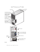
Dell™ Dimension™ 5100 cover latch release Service Tag CD or DVD eject button CD or DVD activity light FlexBay for optional floppy drive or Media Card Reader microphone connector headphone connector diagnostic lights hard-drive activity light power button/ power activity light USB 2.0 connectors (2) power connector sound connectors (integrated) (5) VGA video connector (integrated) network adapter USB 2.0 connectors (5) card slots for PCI Express x16 (1), PCI (2), PCI Express x1 (1) Model DCSM w w w.
Notes, Notices, and Cautions NOTE: A NOTE indicates important information that helps you make better use of your computer. NOTICE: A NOTICE indicates either potential damage to hardware or loss of data and tells you how to avoid the problem. CAUTION: A CAUTION indicates a potential for property damage, personal injury, or death. If you purchased a Dell™ n Series computer, any references in this document to Microsoft® Windows® operating systems are not applicable.
Contents Finding Information 1 . . . . . . . . . . . . . . . . . . . . . . . . . . . . 9 Setting Up and Using Your Computer Setting Up a Printer . . . . . . . . . . . . . . . . . . . . . . . . . . . . 11 Printer Cable . . . . Connecting a Printer . . . . . . . . . . . . . . . . . . . . . . . . . . . . . . . . . . . . . . . . . . . . . . . . . . 11 12 Connecting to the Internet . . . . . . . . . . . . . . . . . . . . . . . . . 12 . . . . . . . . . . . . . . . . . . 13 . . . . . . . . . . . . .
2 Solving Problems Troubleshooting Tips . . . . . . . . . . . . . . . . . . . . . . . . . . . . 27 . . . . . . . . . . . . . . . . . . . . . . . . . . . . . 27 . . . . . . . . . . . . . . . . . . . . . . . . . . . . . . 27 . . . . . . . . . . . . . . . . . . . . . . . . . . . . . . . . . . . . . . . . . . . . 28 29 . . . . . . . . . . . . . . . . . . . 29 . . . . . . . . . . . . . . . . . . . . . . . . . . . . . . 30 . . . . . . . . . . . . . . . . . . . . . . . 31 . . . . . . . . . . . . .
3 Troubleshooting Tools Diagnostic Lights . . . . . . . . . . . . . . . . . . . . . . . . . . . . . 43 Dell Diagnostics . . . . . . . . . . . . . . . . . . . . . . . . . . . . . . 46 Dell Diagnostics Main Menu . Drivers . . . . . . . . . . . . . . . . . . . . . 46 . . . . . . . . . . . . . . . . . . . . . . . . . . . . . . . . . . 47 What Is a Driver? . Identifying Drivers. Reinstalling Drivers . . . . . . . . . . . . . . . . . . . . . . . . . . . . . . . . . . . . . . . . . . . . . . . . . . .
Drive Panel . . . . . . . . . . . . . . . . . . . . . . . . . . . . . . . . Removing the Drive Panel . . . . Removing the Drive-Panel Insert . Replacing the Drive-Panel Insert . Replacing the Drive Panel. . . . . Drives . . . . . . . . . . . . . . . . . . . . . . . . . . . . . . . . . . . . . . . 76 77 77 78 . . . . . . . . . . . . . . . . . . . . . . . . . . . . . . . . . . 79 . . . . . . . . . . . . . . . . . . . . . . . . . . . . . . . . . . . . . . IDE Drive Addressing . . . . . . . . . . .
5 Appendix Specifications . System Setup . . . . . . . . . . . . . . . . . . . . . . . . . . . . . . . . . . . . . . . . . . . . . . . . . . . . . . . . . . . . Overview . . . . . . . Entering System Setup. System Setup Options . Boot Sequence . . . . . . . . . . . . . . . . . . . . . . . . . . . 99 103 . . . . . . . . . . . . . . . . . . . . . . . 103 103 105 109 . . . . . . . . . . . . . . . . . . . . . . 111 Clearing CMOS Settings . . . . . . . . . . . . . . . . . . . . . . . . .
Contents
Finding Information NOTE: Additional documentation may be included with your computer, depending on your country.
What Are You Looking For? Find It Here • Service Tag and Express Service Code • Microsoft Windows License Label Service Tag and Microsoft Windows License These labels are located on your computer. • Use the Service Tag to identify your computer when you use support.dell.com or contact technical support. • Enter the Express Service Code to direct your call when contacting technical support. The Express Service Code is not available in all countries.
Setting Up and Using Your Computer Setting Up a Printer NOTICE: Complete the operating system setup before you connect a printer to the computer. See the documentation that came with the printer for setup information, including how to: • Obtain and install updated drivers • Connect the printer to the computer • Load paper and install the toner or ink cartridge • Contact the printer manufacturer for technical assistance Printer Cable Your printer connects to your computer with a USB cable.
Connecting a Printer NOTE: You can connect USB devices while the computer is turned on. 1 Complete the operating system setup, if you have not already done so. 2 Install the printer driver if necessary. See the documentation that came with your printer. 3 Attach the USB printer cable to the USB connectors on the computer and the printer. The USB connectors fit only one way.
If you are using a dial-up connection, connect a telephone line to the modem connector on your computer and to the telephone wall jack before you set up your Internet connection. If you are using a DSL or cable modem connection, contact your ISP for setup instructions. Setting Up Your Internet Connection To set up an AOL or MSN connection: 1 Save and close any open files, and exit any open programs. 2 Double-click the MSN Explorer or AOL icon on the Microsoft® Windows® desktop.
Playing CDs and DVDs NOTICE: Do not press down on the CD or DVD tray when you open or close it. Keep the tray closed when you are not using the drive. NOTICE: Do not move the computer when you are playing CDs or DVDs. 1 Press the eject button on the front of the drive. 2 Place the disc, label side up, in the center of the tray. 3 Press the eject button or gently push in the tray. To format CDs for storing data, to create music CDs, or to copy CDs, see the CD software that came with your computer.
A DVD player includes the following basic buttons: Stop Restart the current chapter Play Fast forward Pause Fast reverse Advance a single frame while in pause mode Go to the next title or chapter Continuously play the current title or chapter Go to the previous title or chapter Eject For more information on playing CDs or DVDs, click Help on the CD or DVD player (if available). Adjusting the Volume NOTE: When the speakers are muted, you do not hear the CD or DVD playing.
4 In the Display Properties window, click and drag the bar in Screen resolution to change the setting to 800 by 600 pixels. 5 Click the drop-down menu under Color quality, and then click Medium (16 bit). 6 Click OK. Copying CDs and DVDs NOTE: Please observe all copyright laws when creating CDs or DVDs. This section applies only to computers that have a CD-RW, DVD+/-RW, or CD-RW/DVD (combo) drive. NOTE: The types of CD or DVD drives offered by Dell may vary by country.
Using Blank CDs and DVDs CD-RW drives can write to CD recording media only (including high-speed CD-RW) while DVD-writable drives can write to both CD and DVD recording media. Use blank CD-Rs to record music or permanently store data files. After creating a CD-R, you cannot write to that CD-R again (see the Sonic documentation for more information). Use blank CD-RWs to write to CDs or to erase, rewrite, or update data on CDs. Blank DVD+/-Rs can be used to permanently store large amounts of information.
• Commercially available DVD players used in home theater systems may not support all available DVD formats. For a list of formats supported by your DVD player refer to the documentation provided with your DVD player or contact the manufacturer. • Do not burn a blank CD-R or CD-RW to its maximum capacity; for example, do not copy a 650-MB file to a blank 650-MB CD. The CD-RW drive needs 1-2 MB of the blank space to finalize the recording.
xD-Picture Card and SmartMedia (SMC) CompactFlash Type I and II (CF I/II) and MicroDrive Card Memory Stick (MS/MS Pro) SecureDigital Card (SD)/ MultiMediaCard (MMC) To use the Media Card Reader: 1 Check the media or card to determine the proper orientation for insertion. 2 Slide the media or card into the appropriate slot until it is completely seated in the connector. If you encounter resistance, do not force the media or card. Check the card orientation and try again.
Connecting Two Monitors With VGA Connectors 1 Follow the procedures in "Before You Begin" on page 53. NOTE: If your computer has integrated video, do not connect either monitor to the integrated video connector. If the integrated video connector is covered by a cap, do not remove the cap to connect the monitor or the monitor will not function. 2 Connect one of the monitors to the VGA (blue) connector on the back of the computer.
Connecting a TV NOTE: You must purchase an S-video cable, available at most consumer electronics stores, to connect a TV to your computer. It is not included with your computer. 1 Follow the procedures in "Before You Begin" on page 53. 2 Connect one end of the S-video cable to the optional TV-OUT connector on the back of the computer. 3 Connect the other end of the S-video cable to the S-video input connector on your TV. 4 Connect the VGA or DVI monitor.
network adapter connector network adapter connector on computer network device network cable Network Setup Wizard The Microsoft® Windows® XP operating system provides a Network Setup Wizard to guide you through the process of sharing files, printers, or an Internet connection between computers in a home or small office. 1 Click the Start button, point to All Programs→ Accessories→ Communications, and then click Network Setup Wizard. 2 On the welcome screen, click Next.
Standby Mode Standby mode conserves power by turning off the display and the hard drive after a time-out. When the computer exits from standby mode, it returns to the operating state it was in before it entered standby mode. To set standby mode to automatically activate after a defined period of inactivity: 1 Click the Start button and click Control Panel. 2 Under Pick a category, click Performance and Maintenance. 3 Under or pick a Control Panel icon, click Power Options.
Power Schemes Tab Each standard power setting is called a scheme. If you want to select one of the standard Windows schemes installed on your computer, choose a scheme from the Power schemes drop-down menu. The settings for each scheme appear in the fields below the scheme name. Each scheme has different settings for starting standby mode or hibernate mode, turning off the monitor, and turning off the hard drive.
Hyper-Threading Hyper-Threading is an Intel® technology that can enhance overall computer performance by allowing one physical processor to function as two logical processors, capable of performing certain tasks simultaneously. It is recommended that you use the Microsoft® Windows® XP Service Pack 1 (SP1) or later operating system because Windows XP is optimized to take advantage of Hyper-Threading technology.
Setting Up and Using Your Computer
Solving Problems Troubleshooting Tips Follow these tips when you troubleshoot your computer: • If you added or removed a part before the problem started, review the installation procedures and ensure that the part is correctly installed. • If a peripheral device does not work, ensure that the device is properly connected. • If an error message appears on the screen, write down the exact message. This message may help technical support personnel diagnose and fix the problem(s).
TE S T T H E D R I V E — • Insert another floppy disk, CD, or DVD to eliminate the possibility that the original one is defective. • Insert a bootable floppy disk and restart the computer. C L E A N T H E D R I V E O R D I S K — See page 113. CHECK THE CABLE CONNECTIONS R U N T H E H A R D W A R E TR O U B L E S H O O T E R — See page 49. R U N T H E D E L L D I A G N O S T I C S — See page 46.
Hard drive problems RUN CHECK DISK — 1 Click the Start button and click My Computer. 2 Right-click Local Disk C:. 3 Click Properties. 4 Click the Tools tab. 5 Under Error-checking, click Check Now. 6 Click Scan for and attempt recovery of bad sectors. 7 Click Start. E-Mail, Modem, and Internet Problems CAUTION: Before you begin any of the procedures in this section, follow the safety instructions in the Product Information Guide. NOTE: Connect the modem to an analog telephone jack only.
VE R I F Y T H A T T H E M O D E M I S C O M M U N I C A T I N G W I T H W I N D O W S — 1 Click the Start button and click Control Panel. 2 Click Printers and Other Hardware. 3 Click Phone and Modem Options. 4 Click the Modems tab. 5 Click the COM port for your modem. 6 Click Properties, click the Diagnostics tab, and then click Query Modem to verify that the modem is communicating with Windows. If all commands receive responses, the modem is operating properly.
N O T E N O U G H M E M O R Y O R R E S O U R C E S . C L O S E S O M E P R O G R A M S A N D T R Y A G A I N — Close all windows and open the program that you want to use. In some cases, you might have to restart your computer to restore computer resources. If so, run the program that you want to use first. O P E R A T I N G S YS T E M N O T F O U N D — Contact Dell (see page 116).
Keyboard Problems CAUTION: Before you begin any of the procedures in this section, follow the safety instructions in the Product Information Guide. CHECK THE KEYBOARD CABLE — • Ensure that the keyboard cable is firmly connected to the computer. • Shut down the computer (see page 53), reconnect the keyboard cable as shown on the setup diagram for your computer, and then restart the computer. • Check the cable connector for bent or broken pins and for damaged or frayed cables. Straighten bent pins.
A program stops responding END THE PROGRAM — 1 Press simultaneously. 2 Click Applications. 3 Click the program that is no longer responding. 4 Click End Task. A program crashes repeatedly NOTE: Software usually includes installation instructions in its documentation or on a floppy disk or CD. C H E C K T H E S O F T W A R E D O C U M E N T A T I O N — If necessary, uninstall and then reinstall the program.
Other software problems CHECK THE SOFTWARE DOCUMENTATION OR CONTACT THE SOFTWARE MANUFACTURER FOR TROUBLESHOOTING INFORMATION — • Ensure that the program is compatible with the operating system installed on your computer. • Ensure that your computer meets the minimum hardware requirements needed to run the software. See the software documentation for information. • Ensure that the program is installed and configured properly. • Verify that the device drivers do not conflict with the program.
Mouse Problems CAUTION: Before you begin any of the procedures in this section, follow the safety instructions in the Product Information Guide. C L E A N T H E M O U S E — See "Mouse" for instructions on cleaning the mouse on page 113. CHECK THE MOUSE CABLE — 1 Remove mouse extension cables, if used, and connect the mouse directly to the computer. 2 Reconnect the mouse cable as shown on the setup diagram for your computer. RESTART THE COMPUTER — 1 Simultaneously press to display the Start menu.
C H E C K T H E N E T W O R K L I G H T S O N T H E B A C K O F T H E C O M P U T E R — If the link integrity light is off, that indicates no network communication exists. Replace the network cable. For a description of network lights, see "Controls and Lights" on page 101.
I F T H E P O W E R L I G H T I S B L I N K I N G A M B E R — The computer is receiving electrical power, but an internal power problem might exist. • Ensure that the voltage selection switch is set to match the AC power at your location (if applicable). • Ensure that the processor power cable is securely connected to the system board (see page 61).
Scanner Problems CAUTION: Before you begin any of the procedures in this section, follow the safety instructions in the Product Information Guide. NOTE: If you need technical assistance for your scanner, contact the scanner’s manufacturer. C H E C K T H E S C A N N E R D O C U M E N T A T I O N — See the scanner documentation for setup and troubleshooting information. U N L O C K T H E S C A N N E R — Ensure that your scanner is unlocked if it has a locking tab or button.
Sound and Speaker Problems CAUTION: Before you begin any of the procedures in this section, follow the safety instructions in the Product Information Guide. No sound from speakers NOTE: The volume control in some MP3 players overrides the Windows volume setting. If you have been listening to MP3 songs, ensure that you did not turn the player volume down or off.
No sound from headphones C H E C K T H E H E A D P H O N E C A B L E C O N N E C T I O N — Ensure that the headphone cable is securely inserted into the headphone connector (see page 55). A D J U S T T H E W I N D O W S V O L U M E C O N T R O L — Click or double-click the speaker icon in the lower-right corner of your screen. Ensure that the volume is turned up and that the sound is not muted.
If the screen is difficult to read C H E C K T H E M O N I T O R S E T T I N G S — See the monitor documentation for instructions on adjusting the contrast and brightness, demagnetizing (degaussing) the monitor, and running the monitor self-test. M O V E T H E S U B W O O F E R A W A Y F R O M T H E M O N I T O R — If your speaker system includes a subwoofer, ensure that the subwoofer is at least 60 cm (2 ft) away from the monitor.
Solving Problems
Troubleshooting Tools Diagnostic Lights CAUTION: Before you begin any of the procedures in this section, follow the safety instructions in the Product Information Guide. To help you troubleshoot a problem, your computer has four lights labeled "1," "2," "3," and "4" on the front panel (see page 57). When the computer starts normally, the lights flash. After the computer starts, all four lights display solid green. If the computer malfunctions, the color and sequence of the lights identify the problem.
Light Pattern 44 Problem Description Suggested Resolution A possible graphics card failure has occurred. • If the computer has a graphics card, remove the card, reinstall it (see page 71), and then restart the computer. • If the problem still exists, install a graphics card that you know works and restart the computer. • If the problem persists or the computer has integrated graphics, contact Dell (see page 116). A possible floppy or hard drive failure has occurred.
Light Pattern Problem Description A possible expansion card failure has occurred. Suggested Resolution 1 Determine if a conflict exists by removing a card (not a graphics card) (see page 66) and restarting the computer. 2 If the problem persists, reinstall the card that you removed, remove a different card, and then restart the computer. 3 Repeat this process for each card.
Dell Diagnostics CAUTION: Before you begin any of the procedures in this section, follow the safety instructions in the Product Information Guide. If you experience a problem with your computer, perform the checks in "Solving Problems" on page 27 and run the Dell Diagnostics before you contact Dell for technical assistance. NOTICE: The Dell Diagnostics works only on Dell™ computers. 1 Turn on (or restart) your computer. 2 When the DELL™ logo appears, press immediately.
3 If you run a test from the Custom Test or Symptom Tree option, click the applicable tab described in the following table for more information. Tab Function Results Displays the results of the test and any error conditions encountered. Errors Displays error conditions encountered, error codes, and the problem description. Help Describes the test and may indicate requirements for running the test. Configuration Displays your hardware configuration for the selected device.
Identifying Drivers If you experience a problem with any device, identify whether the driver is the source of your problem and, if necessary, update the driver. Windows XP 1 Click the Start button and click Control Panel. 2 Under Pick a Category, click Performance and Maintenance. 3 Click System. 4 In the System Properties window, click the Hardware tab. 5 Click Device Manager. 6 Scroll down the list to see if any device has an exclamation point (a yellow circle with a [!]) on the device icon.
Manually Reinstalling Drivers 1 After copying the required driver files to your hard drive, click the Start button and right-click My Computer. 2 Click Properties. 3 Click the Hardware tab and click Device Manager. 4 Double-click the type of device for which you are installing the driver. 5 Double-click the name of the device for which you are installing the driver. 6 Click the Driver tab and click Update Driver. 7 Click Install from a list or specific location (Advanced) and click Next.
Using Microsoft® Windows® XP System Restore The Microsoft Windows XP operating system provides System Restore to allow you to return your computer to an earlier operating state (without affecting data files) if changes to the hardware, software, or other system settings have left the computer in an undesirable operating state. See the Windows Help and Support Center for information on using System Restore. NOTICE: Make regular backups of your data files.
Undoing the Last System Restore NOTICE: Before you undo the last system restore, save and close all open files and exit any open programs. Do not alter, open, or delete any files or programs until the system restoration is complete. 1 Click the Start button, point to All Programs→ Accessories→ System Tools, and then click System Restore. 2 Click Undo my last restoration and click Next.
5 When prompted, click Finish to reboot the computer. NOTE: Do not manually shut down the computer. Click Finish and let the computer completely reboot. 6 When prompted, click Yes. The computer restarts. Because the computer is restored to its original operating state, the screens that appear, such as the End User License Agreement, are the same ones that appeared the first time the computer was turned on. 7 Click Next. The System Restore screen appears and the computer restarts.
Removing and Installing Parts Before You Begin This chapter provides procedures for removing and installing the components in your computer. Unless otherwise noted, each procedure assumes that the following conditions exist: • You have performed the steps in "Turning Off Your Computer" (see page 53) and "Before Working Inside Your Computer" (see page 54). • You have read the safety information in your Dell™ Product Information Guide.
Before Working Inside Your Computer Use the following safety guidelines to help protect your computer from potential damage and to help ensure your own personal safety. CAUTION: Before you begin any of the procedures in this section, follow the safety instructions in the Product Information Guide. CAUTION: Handle components and cards with care. Do not touch the components or contacts on a card. Hold a card by its edges or by its metal mounting bracket.
Front View of the Computer 1 2 3 4 5 6 7 8 9 10 11 12 1 cover latch release Use this latch to remove the cover. See "Removing the Computer Cover" on page 59. 2 location of Service Tag Use the Service Tag to identify your computer when you access the Dell Support website or call technical support. 3 CD or DVD eject button Press to eject a disk from the CD or DVD drive. 4 CD or DVD activity light The drive light is on when the computer reads data from the CD or DVD drive.
8 diagnostic lights (4) Use the lights to help you troubleshoot a computer problem based on the diagnostic code. For more information, see "Diagnostic Lights" on page 43. 9 hard-drive activity light The hard drive activity light is on when the computer reads data from or writes data to the hard drive. The light might also be on when a device such as a CD player is operating. 10 power button, Press the power button to turn on the computer. The light in the center of this button indicates power state.
Back View of the Computer 1 2 3 4 1 voltage selection switch (may not be available on all computers) See the safety instructions in the Product Information Guide for more information. 2 power connector Insert the power cable. 3 back panel connectors Plug USB, audio, and other devices into the appropriate connector. 4 card slots Access connectors for any installed PCI and PCI Express cards.
1 link integrity light • Green — A good connection exists between a 10-Mbps network and the computer. • Orange — A good connection exists between a 100-Mbps network and the computer. • Off — The computer is not detecting a physical connection to the network. 2 network adapter connector To attach your computer to a network or broadband device, connect one end of a network cable to either a network jack or your network or broadband device.
Removing the Computer Cover CAUTION: Before you begin any of the procedures in this section, follow the safety instructions in the Product Information Guide. CAUTION: To guard against electrical shock, always unplug your computer from the electrical outlet before removing the cover. 1 Follow the procedures in "Before You Begin" on page 53. NOTICE: Ensure that sufficient space exists to support the removed cover—at least 30 cm (1 ft) of desk top space.
Inside View of Your Computer CAUTION: Before you begin any of the procedures in this section, follow the safety instructions in the Product Information Guide. Follow the procedures in "Before You Begin" on page 53. power supply system board CD or DVD drive *floppy drive hard drive *May not be present on all computers.
System Board Components processor connector (CPU) password jumper (PSWD) power connector (12V) processor fan connector (FAN) memory module connectors (2, 4) memory module connectors (1, 3) floppy drive connector (DSKT2) battery socket (BATTERY) RTC reset jumper (RTCRST1) PCI connectors (2) SATA connector (SATA2) PCI Express x16 connector (PEG) SATA connector (SATA0) PCI Express x1 connector (PCI_E1) CD/DVD connector (IDE1) front-panel connector (F_PANEL) power connector (POWER) network connector
Memory You can increase your computer memory by installing memory modules on the system board. Your computer supports DDR2 memory. For additional information on the type of memory supported by your computer, see "Memory" on page 99. DDR2 Memory Overview DDR2 memory modules should be installed in pairs of matched memory size, speed, and technology. If the DDR2 memory modules are not installed in matched pairs, the computer will continue to operate, but with a slight reduction in performance.
• If you install mixed pairs of DDR2 400-MHz (PC2-3200) and DDR2 533-MHz (PC2-4300) memory, the modules function at the slowest speed installed. • Be sure to install a single memory module in DIMM connector 1, the connector closest to the processor, before you install modules in the other connectors.
Installing Memory CAUTION: Before you begin any of the procedures in this section, follow the safety instructions in the Product Information Guide. NOTICE: To prevent static damage to components inside your computer, discharge static electricity from your body before you touch any of your computer’s electronic components. You can do so by touching an unpainted metal surface on the computer chassis. 1 Follow the procedures in "Before You Begin" on page 53.
5 Insert the module into the connector until the module snaps into position. If you insert the module correctly, the securing clips snap into the cutouts at each end of the module. 6 Replace the computer cover. NOTICE: To connect a network cable, first plug the cable into the network device and then plug it into the computer. 7 Connect your computer and devices to electrical outlets, and turn them on. 8 Right-click the My Computer icon and click Properties. 9 Click the General tab.
Cards CAUTION: Before you begin any of the procedures in this section, follow the safety instructions in the Product Information Guide. NOTICE: To prevent static damage to components inside your computer, discharge static electricity from your body before you touch any of your computer’s electronic components. You can do so by touching an unpainted metal surface on the computer chassis.
Installing a PCI Card 1 Follow the procedures in "Before You Begin" on page 53. release tab card retention door 2 Gently push the release tab on the card retention door from the inside to pivot the door open. Because the door is captive, it will remain in the open position. 3 If you are installing a new card, remove the filler bracket to create a card-slot opening. Then continue with step 5. 4 If you are replacing a card that is already installed in the computer, remove the card.
6 Place the card in the connector and press down firmly. Ensure that the card is fully seated in the slot.
7 Before you close the card retention door, ensure that: • The tops of all cards and filler brackets are flush with the alignment bar. • The notch in the top of the card or filler bracket fits around the alignment guide. alignment guide alignment bar release tab card retention door 8 Close the card retention door by snapping it into place to secure the card(s). NOTICE: Do not route card cables over or behind the cards.
12 If you installed an add-in network adapter and want to disable the integrated network adapter: a Enter system setup (see page 103), select Integrated NIC, and then change the setting to Off. b Connect the network cable to the add-in network adapter’s connectors. Do not connect the network cable to the integrated connector on the back panel. 13 Install any drivers required for the card as described in the card documentation.
PCI Express Cards Your computer supports one PCI Express x16 card and one PCI Express x1 card. If you are installing or replacing a PCI Express card, follow the procedures in the next section. If you are removing but not replacing a card, see "Removing a PCI Express Card" on page 75. If you are replacing a card, remove the current driver for the card from the operating system. If you are installing or replacing a PCI card, see "Installing a PCI Card" on page 67.
4 If you are installing a new card, remove the filler bracket to create a card-slot opening. Then continue with step 5. 5 If you are replacing a card that is already installed in the computer, remove the card. If necessary, disconnect any cables connected to the card. If your card includes a retention mechanism, remove the top of the retention mechanism by pressing the tab and pulling up on the top. Gently pull the securing tab, grasp the card by its top corners, and then ease it out of its connector.
8 Place the card in the connector and press down firmly. Ensure that the card is fully seated in the slot. not fully seated card fully seated card bracket within slot alignment guide bracket caught outside of slot alignment bar 9 If you replaced a card that was already installed in the computer and you removed the retention mechanism, you may reinstall the retention mechanism.
card retention door card retention mechanism release tabs (2) NOTICE: Do not route card cables over or behind the cards. Cables routed over the cards can prevent the computer cover from closing properly or cause damage to the equipment. NOTICE: To connect a network cable, first plug the cable into the network device and then plug it into the computer. 12 Replace the computer cover, reconnect the computer and devices to electrical outlets, and then turn them on.
Removing a PCI Express Card 1 Follow the procedures in "Before You Begin" on page 53. 2 Gently push the release tab on the card retention door from the inside to pivot the door open. Because the door is captive, it will remain in the open position. (See page 67 for an illustration of the card retention door.
Drive Panel CAUTION: Before you begin any of the procedures in this section, follow the safety instructions in the Product Information Guide. CAUTION: To guard against electrical shock, always unplug your computer from the electrical outlet before removing the cover. Removing the Drive Panel 1 Follow the procedures in "Before You Begin" on page 53.
Removing the Drive-Panel Insert drive panel insert tab drive panel drive panel insert 1 Turn the drive panel sideways and find the tip of the drive-panel insert tab that latches over a tab on the right side of the drive panel. 2 Pull the inner tip of the drive-panel insert tab away from the drive panel. 3 Pivot the drive-panel insert out and away from the drive panel. 4 Set the drive-panel insert aside in a secure location.
Replacing the Drive Panel. 1 Follow the procedures in "Before You Begin" on page 53. sliding plate lever sliding plate drive panel 2 Align the drive panel tabs with the side-door hinges. 3 Rotate the drive panel toward the computer until it snaps into place on the front panel.
Drives Your computer supports a combination of these devices: • Up to two serial ATA hard drives • One FlexBay drive (may contain an optional floppy drive or an optional Media Card Reader) • Up to two CD or DVD drives CD/DVD drive(s) FlexBay for optional floppy drive or Media Card Reader hard drive(s) Connect CD/DVD drives to the connector labeled "IDE1" on the system board. Serial ATA hard drives should be connected to the connectors labeled "SATA0" or "SATA2" on the system board.
Drive Interface Connectors Most interface connectors are keyed for correct insertion; that is, a notch or a missing pin on one connector matches a tab or a filled-in hole on the other connector. Keyed connectors ensure that the pin1 wire in the cable (indicated by the colored stripe along one edge of the IDE cable—serial ATA cables do not use a colored stripe) goes to the pin-1 end of the connector.
Connecting and Disconnecting Drive Cables When removing an IDE drive data cable, grasp the colored pull tab and pull until the connector detaches. When connecting and disconnecting a serial ATA data cable, disconnect the cable using the pull-tab. Like IDE connectors, the serial ATA interface connectors are keyed for correct insertion; that is, a notch or a missing pin on one connector matches a tab or a filled-in hole on the other connector.
Removing a Hard Drive 1 Follow the procedures in "Before You Begin" on page 53. 2 Disconnect the power and data cables from the drive. NOTICE: Use the pull-tab to remove the data cable from your hard drive or from the system board. serial ATA data cable power cable 3 Press in on the blue tabs on each side of the drive and slide the drive up and out of the computer.
Installing a Hard Drive 1 Unpack the replacement hard drive, and prepare it for installation. 2 Check the documentation for the drive to verify that it is configured for your computer. NOTE: If your replacement hard drive does not have the hard drive bracket attached, remove the bracket from the old drive by unsnapping it from the drive. Snap the bracket onto the new drive. drive hard drive bracket 3 Gently slide the drive into place until you feel a click or feel the drive securely installed.
5 Check all connectors to be certain that they are properly cabled and firmly seated. 6 Replace the computer cover (page 98). NOTICE: To connect a network cable, first plug the cable into the network wall jack and then plug it into the computer. 7 Connect your computer and devices to electrical outlets, and turn them on. See the documentation that came with the drive for instructions on installing any software required for drive operation.
Floppy Drive CAUTION: Before you begin any of the procedures in this section, follow the safety instructions in the Product Information Guide. CAUTION: To guard against electrical shock, always unplug your computer from the electrical outlet before removing the cover. NOTE: If you are adding a floppy drive, see "Installing a Floppy Drive" on page 87. Removing a Floppy Drive 1 Follow the procedures in "Before You Begin" on page 53. 2 Remove the drive panel (see page 76).
4 Slide the drive latch release toward the bottom of the computer and, without releasing the drive latch release, slide the floppy drive out through the front of the computer.
Installing a Floppy Drive NOTE: In the event the replacement or new floppy drive does not have the shoulder screws, use the screws located within the drive panel insert. drive screws (4) 1 Follow the procedures in "Before You Begin" on page 53. 2 Remove the drive panel (see page 76). 3 Gently slide the drive into place until you feel a click or feel the drive securely installed.
5 Connect the other end of the data cable to the connector labeled "DSKT2" on the system board (see page 61) and route the cable through the clip on the shroud. power cable data cable 6 If you are installing a new floppy drive rather than replacing a drive, remove the drive-panel inserts (see page 85). 7 Check all cable connections, and fold cables out of the way to provide airflow for the fan and cooling vents. 8 Replace the drive panel (see page 78). 9 Replace the computer cover (see page 98).
Media Card Reader For information on using the Media Card Reader, see "Using a Media Card Reader (Optional)" on page 18. Removing a Media Card Reader CAUTION: Before you begin any of the procedures in this section, follow the safety instructions located in the Product Information Guide. NOTICE: To prevent static damage to components inside your computer, discharge static electricity from your body before you touch any of your computer’s electronic components.
5 Disconnect the FlexBay USB cable on the back of the Media Card Reader from the Media Card Reader connector on the system board (see page 61) and route the cable through the cable routing clip. drive latch release sliding plate Media Card Reader 6 Slide the drive latch release toward the bottom of the computer and, without releasing the drive latch release, slide the Media Card Reader out through the front of the computer. 7 Replace the drive panel (see page 78).
Installing a Media Card Reader CAUTION: Before you begin any of the procedures in this section, follow the safety instructions located in the Product Information Guide. NOTICE: To prevent static damage to components inside your computer, discharge static electricity from your body before you touch any of your computer’s electronic components. You can do so by touching an unpainted metal surface on the computer chassis. 1 Follow the procedures in "Before You Begin" on page 53.
7 Connect the FlexBay USB cable to the back of the Media Card Reader and to the Media Card Reader connector on the system board (see page 61). FlexBay USB cable Media Card Reader 8 Insert the Media Card Reader and slide it into place until it is fully seated. 9 Route the FlexBay USB cable through the cable routing clip. 10 Replace the computer cover (see page 98).
CD/DVD Drive CAUTION: Before you begin any of the procedures in this section, follow the safety instructions located in the Product Information Guide. CAUTION: To guard against electrical shock, always unplug your computer from the electrical outlet before removing the cover. Removing a CD/DVD Drive 1 Follow the procedures in "Before You Begin" on page 53. 2 Remove the computer cover (see page 59). 3 Remove the drive panel (see page 76). 4 Disconnect the power and data cables from the back of the drive.
5 Slide the drive latch release toward the bottom of the computer and, without releasing the drive latch release, slide the CD/DVD drive out through the front of the computer.
Installing a CD/DVD Drive 1 Follow the procedures in "Before You Begin" on page 53. 2 If you are installing a new CD/DVD drive rather than replacing a drive, remove the drive-panel inserts (see page 77). 3 Gently slide the drive into place until you feel a click or feel the drive securely installed. NOTE: If you are installing a new CD/DVD drive rather than replacing a drive, remove the drive panel inserts and slide the drive into place.
4 Connect the power and data cables to the drive. power cable data cable 5 Check all cable connections, and fold cables out of the way to provide airflow for the fan and cooling vents. 6 Replace the computer cover (see page 98). 7 Replace the drive panel (see page 78). NOTICE: To connect a network cable, first plug the cable in to the network device and then plug it in to the computer. 8 Connect your computer and devices to their electrical outlets, and turn them on.
Battery Replacing the Battery CAUTION: Before you begin any of the procedures in this section, follow the safety instructions located in the Product Information Guide. NOTICE: To prevent static damage to components inside your computer, discharge static electricity from your body before you touch any of your computer’s electronic components. You can do so by touching an unpainted metal surface on the computer chassis. A coin-cell battery maintains computer configuration, date, and time information.
6 Replace the computer cover (see page 98). NOTICE: To connect a network cable, first plug the cable into the network device and then plug it into the computer. 7 Connect your computer and devices to electrical outlets, and turn them on. 8 Enter system setup (see page 103) and restore the settings you recorded in step 1. 9 Properly dispose of the old battery. See the Product Information Guide for battery disposal information.
Appendix Specifications Processor Processor type Intel® Pentium® 4 with Hyper-Threading technology NOTE: Not all Pentium 4 processors support Hyper-Threading technology.
Video Type Integrated Intel Graphics Media Accelerator 950 (GMA950) Audio Type Sigmatel STAC9220 Expansion Bus Bus type Bus speed PCI 2.
Connectors External connectors: Video 15-hole connector Network adapter RJ-45 connector USB two front-panel and five back-panel USB 2.
Power DC power supply: Wattage 305 W Heat dissipation 560.5 BTU/hr Voltage (see the safety instructions 90 to 135 V and 180 to 265 V at 50/60 Hz located in the Product Information Guide for important voltage setting information) Backup battery 3-V CR2032 lithium coin cell Physical Height 43.8 cm (17.25 inches) Width 41.1 cm (16.19 inches) Depth 18.7 cm (7.38 inches) Weight 14.
System Setup Overview Use system setup as follows: • To change the system configuration information after you add, change, or remove any hardware in your computer • To set or change a user-selectable option such as the user password • To read the current amount of memory or set the type of hard drive installed Before you use system setup, it is recommended that you write down the system setup screen information for future reference.
System Setup Screens The system setup screen displays current or changeable configuration information for your computer.
System Setup Options NOTE: Depending on your computer and installed devices, the items listed in this section may not appear, or may not appear exactly as listed. System System Info Displays the System name, BIOS Version number, BIOS Date, Service Tag, Express Service Code, and Asset Tag.
Drives Diskette Drive (Internal default) Drives 0 through 3 (On default) Enables and disables the floppy drives and sets read permission for the internal floppy drive. Off disables all floppy drives. USB enables the USB floppy drive. Internal enables the internal floppy drive. Read Only enables the internal drive controller and allows the internal floppy drive read-only permission. NOTE: Operating systems with USB support will recognize USB floppy drives regardless of this setting.
Video Primary Video (Auto default) Video Memory Size (8 MB default) Specifies which video controller is primary when two video controllers are present on the computer. Auto enables the add-in video controller. Onboard enables the integrated video controller. Configures the system memory allocation reserved for the integrated video controller. Settings are 1MB and 8MB. Performance (On default) Determines whether the physical processor appears as one or two logical processors.
Power Management AC Recovery (Off default) Auto Power On (Off default) Auto Power Time Determines how the system responds when AC power is re-applied after a power loss. Off commands the system to stay off when the power is re-applied. You must press the front-panel power button before the system turns on. On commands the system to turn on when the power is re-applied. Last commands the system to return to the last power state the system was in just before it was turned off.
POST Behavior Fastboot (On default) Numlock Key (On default) When enabled, this feature reduces computer startup time by bypassing some compatibility steps. Off does not skip any steps during computer startup. On starts the system more quickly. Determines the functionality of the numeric keys on the right side of your keyboard. Off commands the right keypad keys to function as arrows. On commands the right keypad keys to function as numbers.
Changing Boot Sequence for the Current Boot You can use this feature, for example, to restart your computer to a USB device such as a floppy drive, memory key, or CD-RW drive. NOTE: If you are booting to a USB floppy drive, you must first set the floppy drive to OFF in system setup (see page 103). 1 If you are booting to a USB device, connect the USB device to a USB connector (see page 101). 2 Turn on (or restart) your computer.
Clearing Forgotten Passwords CAUTION: Before you begin any of the procedures in this section, follow the safety instructions located in the Product Information Guide. 1 Follow the procedures in "Before You Begin" on page 53. 2 Locate the 3-pin password jumper (PSWD) on the system board (see page 61), and attach the jumper plug to pins 2 and 3 to clear the password. NOTE: When you receive your computer, the jumper plug is attached to pins 1 and 2. 3 Close the computer cover (see page 98).
7 Disconnect the computer power cable from the electrical outlet, and press the power button to ground the system board. 8 Open the computer cover (see page 59). 9 Locate the 3-pin password jumper (PSWD) on the system board (see page 61) and attach the jumper to pins 1 and 2 to reenable the password feature. 10 Close the computer cover (see page 98). NOTICE: To connect a network cable, first plug the cable into the network device and then plug it into the computer.
Cleaning Your Computer CAUTION: Before you begin any of the procedures in this section, follow the safety instructions located in the Product Information Guide. Computer, Keyboard, and Monitor CAUTION: Before you clean your computer, disconnect the computer from the electrical outlet. Clean your computer with a soft cloth dampened with water. Do not use liquid or aerosol cleaners, which may contain flammable substances.
CDs and DVDs NOTICE: Always use compressed air to clean the lens in the CD/DVD drive, and follow the instructions that come with the compressed air. Never touch the lens in the drive. If you notice problems, such as skipping, with the playback quality of your CDs or DVDs, try cleaning the discs. 1 Hold the disc by its outer edge. You can also touch the inside edge of the center hole. NOTICE: To prevent damaging the surface, do not wipe in a circular motion around the disc.
Definition of "Third-Party" Software and Peripherals Third-party software and peripherals include any peripheral, accessory, or software program sold by Dell not under the Dell brand (printers, scanners, cameras, games, and so on). Support for all third-party software and peripherals is provided by the original manufacturer of the product. FCC Notices (U.S. Only) Most Dell computer systems are classified by the Federal Communications Commission (FCC) as Class B digital devices.
Class B This equipment has been tested and found to comply with the limits for a Class B digital device pursuant to Part 15 of the FCC Rules. These limits are designed to provide reasonable protection against harmful interference in a residential installation. This equipment generates, uses, and can radiate radio frequency energy and, if not installed and used in accordance with the manufacturer’s instruction manual, may cause interference with radio communications.
When you need to contact Dell, use the electronic addresses, telephone numbers, and codes provided in the following table. If you need assistance in determining which codes to use, contact a local or an international operator.
Country (City) International Access Code Country Code City Code Department Name or Service Area, Website and E-Mail Address Area Codes, Local Numbers, and Toll-Free Numbers Austria (Vienna) Website: support.euro.dell.com International Access Code: 900 E-mail: tech_support_central_europe@dell.
Country (City) International Access Code Country Code City Code Department Name or Service Area, Website and E-Mail Address Area Codes, Local Numbers, and Toll-Free Numbers Brunei Customer Technical Support (Penang, Malaysia) 604 633 4966 Country Code: 673 Customer Service (Penang, Malaysia) 604 633 4949 Transaction Sales (Penang, Malaysia) 604 633 4955 Canada (North York, Ontario) Online Order Status: www.dell.
Country (City) International Access Code Country Code City Code Department Name or Service Area, Website and E-Mail Address China (Xiamen) Technical Support website: support.dell.com.cn Country Code: 86 Technical Support E-mail: cn_support@dell.com City Code: 592 Customer Care E-mail: customer_cn@dell.
Country (City) International Access Code Country Code City Code Department Name or Service Area, Website and E-Mail Address Area Codes, Local Numbers, and Toll-Free Numbers Czech Republic (Prague) Website: support.euro.dell.com International Access Code: 00 E-mail: czech_dell@dell.com Country Code: 420 Technical Support 22537 2727 Customer Care 22537 2707 Fax 22537 2714 Tech Fax 22537 2728 Switchboard 22537 2711 Denmark (Copenhagen) Website: support.euro.dell.
Country (City) International Access Code Country Code City Code Department Name or Service Area, Website and E-Mail Address Area Codes, Local Numbers, and Toll-Free Numbers France (Paris) (Montpellier) Website: support.euro.dell.com International Access Code: 00 E-mail: support.euro.dell.
Country (City) International Access Code Country Code City Code Department Name or Service Area, Website and E-Mail Address Area Codes, Local Numbers, and Toll-Free Numbers Greece Website: support.euro.dell.com International Access Code: 00 E-mail: support.euro.dell.
Country (City) International Access Code Country Code City Code Department Name or Service Area, Website and E-Mail Address Area Codes, Local Numbers, and Toll-Free Numbers Ireland (Cherrywood) Website: support.euro.dell.com International Access Code: 16 E-mail: dell_direct_support@dell.com Country Code: 353 Technical Support for Inspiron XPS computers only 1850 200 722 City Code: 1 Technical Support for all other Dell computers 1850 543 543 U.K. Technical Support (dial within U.K.
Country (City) International Access Code Country Code City Code Department Name or Service Area, Website and E-Mail Address Japan (Kawasaki) Website: support.jp.dell.
Country (City) International Access Code Country Code City Code Latin America Department Name or Service Area, Website and E-Mail Address Area Codes, Local Numbers, and Toll-Free Numbers Customer Technical Support (Austin, Texas, U.S.A.) 512 728-4093 Customer Service (Austin, Texas, U.S.A.) 512 728-3619 Fax (Technical Support and Customer Service) (Austin, Texas, U.S.A.) 512 728-3883 Sales (Austin, Texas, U.S.A.) 512 728-4397 SalesFax (Austin, Texas, U.S.A.
Country (City) International Access Code Country Code City Code Mexico Department Name or Service Area, Website and E-Mail Address Customer Technical Support 001-877-384-8979 or 001-877-269-3383 International Access Code: 00 Country Code: 52 Area Codes, Local Numbers, and Toll-Free Numbers 50-81-8800 Sales or 01-800-888-3355 Customer Service 001-877-384-8979 or 001-877-269-3383 50-81-8800 Main or 01-800-888-3355 General Support toll-free: 1-866-278-6822 Netherlands Antilles General Support 00
Country (City) International Access Code Country Code City Code Department Name or Service Area, Website and E-Mail Address Area Codes, Local Numbers, and Toll-Free Numbers 001-800-220-1006 Nicaragua General Support Norway (Lysaker) Website: support.euro.dell.com International Access Code: 00 E-mail: support.euro.dell.
Country (City) International Access Code Country Code City Code Department Name or Service Area, Website and E-Mail Address Area Codes, Local Numbers, and Toll-Free Numbers Singapore (Singapore) Website: support.ap.dell.
Country (City) International Access Code Country Code City Code Department Name or Service Area, Website and E-Mail Address Area Codes, Local Numbers, and Toll-Free Numbers Spain (Madrid) Website: support.euro.dell.com International Access Code: 00 E-mail: support.euro.dell.
Country (City) International Access Code Country Code City Code Department Name or Service Area, Website and E-Mail Address Area Codes, Local Numbers, and Toll-Free Numbers Taiwan Website: support.ap.dell.com International Access Code: 002 E-mail: ap_support@dell.
Country (City) International Access Code Country Code City Code Department Name or Service Area, Website and E-Mail Address Area Codes, Local Numbers, and Toll-Free Numbers U.K. (Bracknell) Website: support.euro.dell.com International Access Code: 00 Customer Care website: support.euro.dell.com/uk/en/ECare/Form/Home.asp Country Code: 44 City Code: 1344 Uruguay 132 E-mail: dell_direct_support@dell.
Country (City) International Access Code Country Code City Code Department Name or Service Area, Website and E-Mail Address Area Codes, Local Numbers, and Toll-Free Numbers U.S.A.
Appendix
Index A audio.
Index drives, 79 hard drive, 81 installing CD/DVD, 95 installing floppy, 87 installing hard drive, 83 problems, 27 removing CD/DVD, 93 removing floppy, 85 removing hard drive, 82 second hard drive, 84 serial ATA, 81 DVD drive problems, 28 DVDs, 16 playing, 14 floppy drive installing, 87 removing, 85 L H latch release cover, 55 hard drive activity light, 56 installing, 83 installing second, 84 problems, 29 removing, 82 hardware Dell Diagnostics, 46 Hardware Troubleshooter, 49 headphone connector,
monitor blank, 40 clone mode, 21 connect DVI, 19-20 connect TV, 19, 21 connect two, 19-20 connect VGA, 19-20 display settings, 21 extended desktop mode, 21 hard to read, 41 motherboard.
Index S safety instructions, 9 SATA. See serial ATA scanner problems, 38 serial ATA, 81 support contacting Dell, 116 policy, 114 support.dell.