
Owners Manual
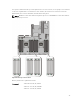

channel 3: slots A4, A8, and A12
Processor 2 channel 0: slots B1, B5, and B9
channel 1: slots B2, B6, and B10
channel 2: slots B3, B7, and B11
channel 3: slots B4, B8, and B12
Mode-specific guidelines
Four memory channels are allocated to each processor. The allowable configurations depend on the
memory mode selected.
NOTE: x4 and x8 DRAM based DIMMs can be mixed providing support for RAS features. However,
all guidelines for specific RAS features must be followed. x4 DRAM based DIMMs retain Single
Device Data Correction (SDDC) in memory optimized (independent channel) mode. x8 DRAM based
DIMMs require Advanced ECC mode to gain SDDC.
The following sections provide additional slot population guidelines for each mode.
Memory optimized (independent channel) mode
This mode supports SDDC only for memory modules that use x4 device width, and the mode does not
impose any specific slot population requirements.
Memory configuration
The following table shows the memory configuration for a two processor configuration.
NOTE: 2R in the following table indicates dual ranked DIMMs.
Table 1. Memory configuration
Configuratio
n
System
Capacity
(in GB)
DIMM
Size (in
GB)
Number
of
DIMMs
DIMM Rank,
Organization,
and Frequency
DIMM Slot Population
Standard 64 8 8
2R, x8, 1600
MT/s,
A1, A2, A3, A4
B1, B2, B3, B4
High capacity 128 16 8
2R, x8, 1600
MT/s,
A1, A2, A3, A4
B1, B2, B3, B4
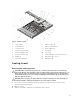
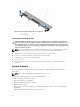
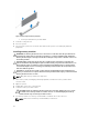
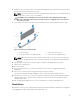
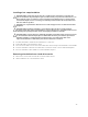
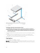
Removing memory modules
WARNING: The memory modules are hot to the touch for some time after the system has been
powered down. Allow time for the memory modules to cool before handling them. Handle the
memory modules by the card edges and avoid touching the components or metallic contacts on
the memory module.
34