
Owners Manual


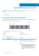
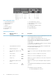

Figure 2. Back panel features
1. System identification button 2. System identification connector
3. iDRAC8 Enterprise port 4. Half-height PCIe expansion card slot
5. Serial connector 6. Video connector
7. USB port 8. Full-height PCIe expansion card slot
9. Ethernet connector 10. Power supply unit 1
11. Power supply unit 2 12. vFlash media card slot
13. Hard drive
Table 2. Back panel features
Item Indicator, button, or
connector
Icon Description
1 System identification button The identification buttons on the front and back panels can be used
to locate a particular system within a rack.
Press to toggle the system identification (ID) on or off.
If the system stops responding during POST, press and hold the
system ID button for more than five seconds to enter BIOS
progress mode.
To reset iDRAC (if not disabled in F2 iDRAC set up) press and hold
the button for more than 15 seconds.
2 System identification connector Connects the optional system status indicator assembly through
the optional cable management arm.
3 iDRAC8 Enterprise port Dedicated management port.
4 Half-height PCIe expansion card
slot (3)
Enables you to connect up to 3 half-height PCI Express expansion
cards.
5 Serial connector Enables you to connect a serial device to the system.
6 Video connector Enables you to connect a VGA display to the system.
7 USB port (2) Enables you to connect USB devices to the system. The ports are
USB 3.0-compliant.
8 Full-height PCIe expansion card
slot (3)
Enables you to connect up to 3 full-height PCI Express expansion
cards.
9 Ethernet connector (4) Four integrated 10/100/1000 Mbps Network Interface Card (NIC)
connectors
or
Four integrated connectors that include:
• Two 10/100/1000 Mbps NIC connectors
10 Dell DR4300e system overview