Setting Up the Dell™ DR Series System as a CIFS or VTL Backup Target on EMC® Networker® Dell Engineering June 2015 A Dell Technical White Paper
Revisions Date Description January 2014 Initial release April 2015 Added VTL Content for v3.2 Release June 2015 Added content for configuring an iSCSI target for Linux THIS WHITE PAPER IS FOR INFORMATIONAL PURPOSES ONLY, AND MAY CONTAIN TYPOGRAPHICAL ERRORS AND TECHNICAL INACCURACIES. THE CONTENT IS PROVIDED AS IS, WITHOUT EXPRESS OR IMPLIED WARRANTIES OF ANY KIND. © 2015 Dell Inc. All rights reserved.
Table of contents Executive summary ................................................................................................................................................................................... 4 1 Installing and configuring the DR Series system ....................................................................................................................... 5 2 Creating and configuring CIFS target container(s) for Networker......................................................
Executive summary This paper provides information about how to set up the Dell DR Series system as a backup target for EMC Networker software. This whitepaper is a quick reference guide and does not include all DR Series system deployment best practices. For additional information, see the DR Series system documentation and other data management application best practices whitepapers for your specific DR Series system at: http://www.dell.
1 Installing and configuring the DR Series system 1. Rack and cable the DR Series system and power it on. 2. Initialize the DR Series system. For more information, see following topics “iDRAC Connection”, “Logging in and Initializing the DR Series System”, and “Accessing iDRAC6/iDRAC7 Using RACADM” in the Dell DR Series System Administrator Guide. 3. Log on to iDRAC using the default address 192.168.0.
5. When the virtual console opens, log on to the system as: user: administrator, password: St0r@ge! NOTE: The “0” in the password is the numeral zero. 6. Set the user-defined networking preferences. 7. 6 View the network preferences summary and confirm if the settings are correct.
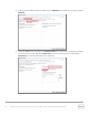
8. Log on to the DR Series system administrator console, using the IP address you just provided for the DR Series system as: user: administrator, password St0r@ge! 9. Join the DR Series system to Active Directory. Note: If you do not want to add the DR Series system to Active Directory, see the DR Series System Owner’s Manual for guest login instructions. a. 7 Select Active Directory from the navigation area of the GUI.
b. Enter your Active Directory credentials to join the DR Series system to a domain.
2 Creating and configuring CIFS target container(s) for Networker 2.1 Creating the network share container for Networker use 1. 9 Create and mount the container by selecting Containers in the navigation area of the GUI, and then clicking Create at the top of the page.
2. Enter a Container Name, select the Marker Type as Networker, and select the Connection Type as NFS/CIFS. 3. Under the CIFS section, note down the CIFS share path (this will be used in configuring the device on the Networker server), and select Enable CIFS. For the Client Access section, select either Open Access or manually add clients to the Clients list.
Note: For improved security, Dell recommends adding IP addresses for the backup console (Networker Server), Networker storage nodes, and Networker clients. Not all environments will have all components. 4. Click Create a New Container and confirm that the container is added. 2.2 Configuring the Networker storage node – Windows CIFS 1. Log on to the storage node and click Start > My Computer. 2. Click Map network drive. 3.
4. Select Reconnect at logon. 5. When prompted, enter the CIFS credential to authenticate on the Active Directory domain. The DR Series system container is now mounted to your backup server. 6. If Client Direct is used, make sure all the clients can access the same DR container share using this path. Otherwise, separate Client Direct Paths must be entered with the actual paths that clients use to access the DR container share (please refer to step 10 in the next section Set up Networker). 2.
3. Select Networker and click Next.
4. Click Finish. 5. Right-click and select the newly created Networker application and click Launch Application.
6. In the Devices window, right-click Device in the left panel and click New Device Wizard. 7. 15 Select Advanced File Type Device (AFTD).
8. In the next dialog box, select Device storage is remote from this Storage Node, type in the network path of the DR Series system container share location (if name resolution works, the hostname or FQDN can be used in the server portion of the network path). In the Authentication section, type the CIFS credentials to access the DR Series system share. Click Next. 9. Click New Folder, type an appropriate folder name, select the folder, and click Next.
10. Set the session attributes according to the Networker administration documentation and click Next. If the Client Direct feature will be used, different device path(s) that clients use to access the DR Series system container share can be entered into the Client Direct Paths (please refer to step 6 in the last section Configure Networker Storage Node). If all of the clients are able to access the DR Series system container share using the direct path, there is no need to enter extra client direct paths.
11. The new Networker device should have Pool Type set to Backup. Click Next. 12. Review the configuration and then click Configure.
13. Click Finish. 14. On the Configuration tab, select Clients, right-click the client that will be backed up, select Client Backup Configuration and click New.
15. Go through the process of creating a new backup group. 16. In Specify the Client Backup Options, define the following settings as follows. a. Deduplication should be set as None b. Target Pool should be set as the pool that has the DR Series system device included. c. Client Direct can be enabled if the client is directly backing up data to a preferred DR, thus bypassing the storage node that is managing the DR share.
Setting Up the Dell™ DR Series System as a CIFS or VTL Backup Target on EMC® Networker® | April 2015
Setting Up the Dell™ DR Series System as a CIFS or VTL Backup Target on EMC® Networker® | April 2015
Setting Up the Dell™ DR Series System as a CIFS or VTL Backup Target on EMC® Networker® | April 2015
17. After the backup group is successfully created, click Start to start the backup. 18. Monitor the job status in the Monitoring tab.
2.4 Setting up DR Series system replication and restore from the replication target 2.4.1 Creating a replication relationship between two DR Series systems 1. Create a source container on the source DR Series system. 2. Create a target container on the target DR Series system.
3. On the source DR Series system, go to the Replication menu, and then click Create. 4. Select the newly created container as the source container, and then enter the target DR Series system information.
5. Click Retrieve Container(s), and then select the newly created target container from the list. 6. Click Create Replication.
7. 28 Verify that the replication relationship between the DR Series systems has been created and that the Peer Status is Online.
2.4.2 Restoring from the replication target container 1. Add the target container onto the Networker storage node. Right-Click Device > New Device Properties, and then enter necessary information for the target device. When complete, mount the device. NOTE: Do not label the target device. 2. Unmount the source container.
3. Go to Recover, click +, select a backup source host, and click Next. 4. Select the data set to recover, click Versions to view the Select Versions window, select the data, and click OK. 5. Select the Recovery Options, choose Original path, or enter a new destination path to which to recover data, and click Next.
6. Enter a Recover name, and click Run Recovery.
7. 32 Check the Recovery Results.
3 Creating and configuring iSCSI target container(s) for Networker 3.1 Creating an iSCSI VTL container for Networker use 1. Create and export the iSCSI container by selecting Containers in the left navigation pane of the DR Series system GUI, and click Create at the top of the page. 2. Enter a container name and select the Virtual Tape Library (VTL) container option. Click Next.
3. Select the iSCSI Access Protocol. Specify the DMA Access Control by providing the storage node / media node IP Address, IQN or FQDN. For Marker Type, select Networker. Click Next. 4. Click Create a New Container.
3.1.1 Configuring the iSCSI Networker storage node – Windows iSCSI initiator configuration is a two-step process, consisting of: • • 1. 35 Target discovery. Establishing an iSCSI session with the target using CHAP authentication. Provide the IP or FQN of the DR Series system in the Target field. Click Quick Connect, which results in target discovery, The Quick Connect dialog box lists all available targets on the DR Series system. At this point, the status will be Inactive.
2. Close the dialog box and proceed by selecting the newly discovered target. This target will have an Inactive Status as it requires authentication parameters to be provided for iSCSI login. Select the Target from the list, click the Connect button, and then in the Connect to Target dialog box select the Advanced button.
3. In Advanced Settings, select to Enable CHAP log on and type the User Name and Target Secret / Password. Select OK to save the settings. Refer to Appendix A for further details about accounts and credentials.
The iSCSI target should now appear as connected and the device discovery can now proceed.
4. Open the Server Manager Snap-in and verify that the newly connected devices appear in the Device Manager. Verify that the STK Library and IBM Ultrium-TD4 Device Drivers are installed. Note: (Refer to the link, http://catalog.update.microsoft.com/v7/site/home.aspx for information and assistance in acquiring Microsoft Device Drivers , for example, StorageTek Library Drivers). 3.1.
For example: iscsiadm -m discovery -t st -p 10.8.230.108 3. Enable logon to the DR Series system iSCSI VTL target(s) by using the following command: iscsiadm -m node --portal --login For example: iscsiadm -m node --portal "10.8.230.108:3260" --login 4. Display the open session(s) with DR VTL(s) by using the following command: iscsiadm -m session For example: iscsiadm -m session = tcp: [8] 10.8.230.108:3260,1 iqn.198405.com.dell:dr4000.3071067.interoprhel52n1.30 5.
2. In the Scan for Device dialog box, select the appropriate storage node with the settings to Search all LUNs, Use Persistent Names and Device Scan Type of scsi. 3. After the device scans, the iSCSI VTL should now appear and must be configured for use. Select the library within the Storage Nodes navigation tree and proceed with the Configure Library option. In the Configure Library dialog box, Check All drives and click Start Configuration.
4. The VTL should now show up ready for use. By default, the cleaning option is enabled, which must be disabled. Within the navigation tree, select the Library and Properties option. In the dialog box, disable the Auto-clean option, and omit the default slot and cleanings settings. Click OK to save the changes.
5. After the library has been configured, the individual tape drives must be configured so that they service only one target session at any given time. Multiplexing to virtual tape drives has an adverse effect on deduplication and thus requires that each drive only handle a single target session. 6. Conduct a full inventory of the library. 7. 43 Label all the media with labels and place them in their respective media pools for use.
4 Creating and configuring NDMP target container(s) for Networker 4.1 Creating the NDMP VTL container for Networker use 1. Create and export the iSCSI container by selecting Containers in the navigation area of the GUI, and then clicking Create at the top of the page. 2. In the Create New Container wizard, enter the container name, select the Virtual Tape Library (VTL) container option, and click Next.
3. Select the NDMP Access Protocol. Specify the DMA Access Control information by providing the storage node or, media node IP Address or FQDN. Select the Marker Type as Unix Dump and click Next. 4. Finalize the VTL creation request by clicking Create a New Container.
4.2 Configuring Networker to use the newly created NDMP VTL 1. Add the DR Series system as a storage node via NDMP. a. Navigate to the Devices menu, select the Storage Nodes Sub-Tree object within the EMC Networker navigation pane, and add a new storage node. b. In the Create Storage Node window enter the name of the node (this must be resolvable via DNS or host file resolution). Provide the logon credentials for the ndmp user account on the DR Series system. 2.
3. In the Scan for Device dialog box select the appropriate storage node with the settings to Search all LUNs, Use Persistent Names and Device Scan Type of ndmp.
4. After the device scan, the NDMP VTL should now appear and can be configured for use. Select the library within the storage nodes navigation tree and proceed with the Configure Library option. In the Configure Library dialog box, Check All drives and click the Start Configuration button. 5. The VTL should now appear ready for use. By default, the cleaning option is enabled, and it must be disabled. Within the navigation tree, select the Library, and then select the Properties option.
6. After the library has been configured, the individual tape drives must be configured so that they service only one target session at any given time. Multiplexing to virtual tape drives has an adverse effect on deduplication and thus requires that each drive only handle a single target session.
7. Proceed by conducting a full inventory of the library. 8. Label all the media and place them in their respective media pools for use.
5 Setting up the DR Series system cleaner Performing scheduled disk space reclamation operations are recommended as a method for recovering disk space from system containers in which files are deleted, as a result of deduplication. The cleaner runs during idle time. If your workflow does not have a sufficient amount of idle time on a daily basis, then you should consider scheduling the cleaner to force it to run during a scheduled time.
6 Monitoring deduplication, compression, and performance After backup jobs have run, the DR Series system tracks capacity, storage savings, and throughput on the DR Series system dashboard. This information is valuable in understanding the benefits of the DR Series system. Note: Deduplication ratios increase over time. It is not uncommon to see a 2-4x reduction (25-50% total savings) on the initial backup. As additional full backup jobs are completed, the ratios will increase.
A Managing VTL protocol accounts and credentials A.1 iSCSI account details and management By default the iSCSI Username will be the hostname of the DR and can be confirmed by reviewing the output of the iscsi –account --user command. For example: >iscsi --account --user user: dr9-interop-a7 The default iSCSI Password is “St0r@ge!iscsi”. This can be modified by navigating to the Clients Navigation option and selecting the iSCSI tab under the Clients menu.
A.2 NDMP account details and management The default username for the NDMP service is “backup_user” and can be confirmed using the web UI interface: Or, by using the following commands: ndmp –show command: administrator@dr9-interop-a7 > ndmp --show NDMP User: backup_user NDMP Port: 10000 The default password is St0r@ge! and can be modified by running the ndmp –setpassword command: > ndmp --setpassword Enter new NDMP password:######### Re-type NDMP password:######### NDMP password successfully updated.
A.
B Adding VTL media B.1 Adding the VTL media to the container To add media to an existing VTL container navigate to the Containers menu option. Select and edit the target VTL container. Use the resulting dialog box field Add More Tape (no of Tape) field to input the number of tapes to add to the VTL container. Alternatively you may also use the “vtl –create_carts” cli command for this operation: > vtl --create_carts --name TEST_VTL_LALA --tapes 10 Created 10 cartridges B.1.
B.2 Updating Networker to identify newly added VTL media After the VTL media has been added to the target VTL container NetWorker must now be updated to be able to use media. Select the VTL and conduct an inventory update. Input the new range created (e.g. 10 new tapes would result in 20 Slots) and select the option to reinitialize the library.