Dell Storage MD1400 -Gehäuse Hardware-Benutzerhandbuch September 2019 Rev.
Anmerkungen, Vorsichtshinweise und Warnungen ANMERKUNG: Eine ANMERKUNG liefert wichtige Informationen, mit denen Sie den Computer besser einsetzen können. VORSICHT: Ein VORSICHTSHINWEIS macht darauf aufmerksam, dass bei Nichtbefolgung von Anweisungen eine Beschädigung der Hardware oder ein Verlust von Daten droht, und zeigt auf, wie derartige Probleme vermieden werden können.
Inhaltsverzeichnis Kapitel 1: Wissenswertes über Ihr Gehäuse........................................................................................5 Abmessungen und Gewicht................................................................................................................................................. 5 Merkmale und Anzeigen auf der Vorderseite.....................................................................................................................
Kapitel 3: Fehlerbehebung am Gehäuse........................................................................................... 30 Sicherheit geht vor – für Sie und das Gehäuse...............................................................................................................30 Fehlerbehebung bei Problemen beim Gehäusestart....................................................................................................... 30 Fehlerbehebung bei unterbrochener Kommunikation......................
1 Wissenswertes über Ihr Gehäuse Themen: • • • • • • • • Abmessungen und Gewicht Merkmale und Anzeigen auf der Vorderseite Funktionen und Anzeigen auf der Frontverkleidung Festplattenlaufwerk-Anzeigemuster Merkmale und Anzeigen auf der Rückseite Gehäuseverwaltungsmodul Betriebsanzeigecodes Weitere nützliche Informationen Abmessungen und Gewicht Tabelle 1.
Elemen Anzeige, Taste oder t Anschluss 3 Symbol LED für Gehäusestatus Beschreibung Die LED für Gehäusestatus leuchtet, wenn die Stromversorgung des Gehäuses eingeschaltet ist. Sie leuchtet während des Normalbetriebs stetig blau. Sie blinkt blau, während ein Host-Server dabei ist, das Gehäuse zu identifizieren, oder wenn die Taste zur Systemidentifizierung gedrückt wurde.
Festplattenlaufwerk-Anzeigemuster Abbildung 4. Festplattenlaufwerk-Anzeigen 1. Festplattenlaufwerk-Aktivitätsanzeige (grün) 2. Anzeige für Festplattenlaufwerksstatus (grün und gelb) 3.
Merkmale und Anzeigen auf der Rückseite Abbildung 5. Merkmale und Anzeigen auf der Rückseite Elemen Anzeige, Taste oder Anschluss t Beschreibung 1 600-W-Netzteil Netzteil oder das Lüftermodul (PS1) Weitere Informationen finden Sie im Abschnitt Netzteilanzeigecodes. 2 Primäres Gehäuseverwaltungsmodul (Enclosure Management Module [EMM 0]) Das EMM erfüllt die folgenden Funktionen: 3 Sekundäres EMM (EMM 1) ● Gehäuseverwaltungsfunktionen für das Gehäuse.
Abbildung 6. Gehäuseverwaltungsmodul Element Anzeige, Taste oder Anschluss Symbol Beschreibung 1, 2, 3, 4, SAS-Schnittstelle (Eingang oder Ausgang) Bietet eine SAS-Kabelverbindung zum Host oder zum nächsthöheren Erweiterungsgehäuse und zu dem nächsttieferen Erweiterungsgehäuse in einer Verkettungsschaltung (Single Port, redundante und Multi-Chain-Konfiguration) 5 USB Mini-B (serieller Debug-Anschluss) Nur für Nutzung durch Techniker.
Betriebsanzeigecodes Abbildung 7. Betriebsanzeigecodes Elemen t LED Farbe Zustand 1 Gleichstromverso rgung Grün ● EIN - Normaler Betrieb. Das Netzteil ist mit dem Gleichstromnetz verbunden und der Netzschalter ist eingeschaltet. Das Netzteilmodul versorgt das Array mit Gleichstrom. ● AUS - Kann folgende Bedeutungen haben: ○ Der Netzschalter ist ausgeschaltet. ○ Das Netzteilmodul ist nicht an die Stromversorgung angeschlossen. ○ Es ist eine Störung aufgetreten.
2 Installation von Gehäusekomponenten Themen: • • • • • • • • Empfohlene Werkzeuge Frontverkleidung (optional) Festplattenlaufwerke Gehäuseverwaltungsmodul Wechselstrom-Netzteil oder Lüftermodul Wissenswertes über Gleichstrom-Netzteile Bedienfeld Rückwandplatine Empfohlene Werkzeuge Für die in diesem Abschnitt beschriebenen Maßnahmen benötigen Sie gegebenenfalls die folgenden Werkzeuge: ● Schlüssel für das Systemschloss ● Kreuzschlitzschraubendreher der Größe 2 ● Erdungsband Frontverkleidung (optional) E
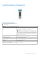
Abbildung 8. Frontverkleidung entfernen und installieren 1. Schloss 2. Frontverkleidung Installieren der Frontverkleidung 1. Haken Sie das rechte Ende der Frontverkleidung am Gehäuse ein. 2. Schwenken Sie das freie Ende der Frontverkleidung auf das System. 3. Sichern Sie die Frontverkleidung mit dem Systemschloss. Festplattenlaufwerke Sicherheit: Modelle AMT, E03J und E04J Die Modelle AMT, E03J und E04J dienen nur der Installation an Orten mit eingeschränktem Zugang entsprechend Klausel 1.2.7.
2. Drücken Sie auf die Freigabelasche und schieben Sie den Festplattenlaufwerkplatzhalter heraus, bis er vollständig aus dem Festplattenlaufwerksschacht entfernt wurde. Abbildung 9. Entfernen und Installieren eines 3,5-Zoll-Laufwerks 1. Festplattenlaufwerkplatzhalter 2. Freigabelasche Installieren eines Festplattenlaufwerksplatzhalters 1. Falls installiert, entfernen Sie die Frontverkleidung. Siehe Entfernen der Frontverkleidung. 2.
Abbildung 10. Festplattenlaufwerk entfernen und installieren a. Entriegelungstaste b. Festplattenlaufwerk c. Griff des Festplattenlaufwerksträgers Installation eines Festplattenlaufwerks VORSICHT: Viele Reparaturen am Computer dürfen nur von einem zertifizierten Servicetechniker ausgeführt werden. Sie sollten nur die Behebung von Störungen sowie einfache Reparaturen unter Berücksichtigung der jeweiligen Angaben in den Produktdokumentationen von Dell durchführen, bzw.
Abbildung 11. Entfernen eines Festplattenlaufwerks aus einem und Installieren in einen 3,5-Zoll-Festplattenlaufwerksträger. 1. Schrauben (4) 2. Festplattenlaufwerk 3. Festplattenlaufwerksträger Installieren eines Festplattenlaufwerks in einem Festplattenlaufwerkträger 1. Führen Sie das Festplattenlaufwerk in den Festplattenlaufwerkträger ein, wobei sich das Anschlussende des Festplattenlaufwerks hinten befindet. 2.
Abbildung 12. Entfernen und Installieren einer EMM-Platzhalterkarte 1. EMM-Platzhalterkarte 2. Sperrklinke Installieren einer EMM-Platzhalterkarte Um eine EMM-Platzhalterkarte zu installieren, richten Sie die Platzhalterkarte auf den EMM-Schacht aus und führen Sie die Platzhalterkarte in das Gehäuse ein, bis sie hörbar einrastet. Entfernen eines EMM VORSICHT: Viele Reparaturen am Computer dürfen nur von einem zertifizierten Servicetechniker ausgeführt werden.
Abbildung 13. EMM entfernen und installieren 1. Freigabehebel 2. EMM 3. Freigabelasche Installieren eines EMMs VORSICHT: Viele Reparaturen am Computer dürfen nur von einem zertifizierten Servicetechniker ausgeführt werden. Sie sollten nur die Behebung von Störungen sowie einfache Reparaturen unter Berücksichtigung der jeweiligen Angaben in den Produktdokumentationen von Dell durchführen, bzw. die elektronischen oder telefonischen Anweisungen des Service- und Supportteams von Dell befolgen.
VORSICHT: Ein einzelnes Netzteil oder Lüftermodul kann für maximal fünf Minuten aus einem eingeschalteten Array entfernt werden. Wird diese Zeit überschritten, kann es zur automatischen Abschaltung des Arrays kommen, um Schäden zu verhindern. Entfernen eines Wechselstrom-Netzteils oder Lüftermoduls ANMERKUNG: Wenn Sie ein aktives Netzteil oder Lüftermodul entfernen, erhöht sich die Lüfterdrehzahl im verbleibenden Modul erheblich, damit für ausreichende Kühlung gesorgt ist.
Abbildung 15. Befestigen der Stromkabel a. Klettstreifen VORSICHT: Wenn Sie das Netzstromkabel anschließen, sichern Sie dieses mit dem Klettband. ANMERKUNG: Wenn das Gehäuse eingeschaltet wird, bleiben alle Betriebsanzeige-LEDs solange dunkel, bis das Stromversorgungskabel an das Netzteil oder Lüftermodul angeschlossen ist und der Netzschalter eingeschaltet ist. 4. Schalten Sie das Netzteil oder Lüftermodul ein.
Element LED Farbe 1 Leistungsabga Grün be ● EIN - Normaler Betrieb. Das Netzteil ist mit dem Gleichstromnetz verbunden und der Netzschalter ist eingeschaltet. Das Netzteilmodul versorgt das Array mit Gleichstrom. ● AUS - Kann folgende Bedeutungen haben: ○ Der Netzschalter ist ausgeschaltet. ○ Das Netzteilmodul ist nicht an die Stromversorgung angeschlossen. ○ Es ist eine Störung aufgetreten. 2 Störung des Netzteilmodul s ● EIN - Störung festgestellt. ● AUS - OK.
Inhalt des Kits ● Molex # 394260002 am Stromverteilerende ● Molex # 39422-0012 Gleichstrom-Gegenstecker Erforderliche Werkzeuge ● Handcrimpzange (Tyco Electronics, 58433-3 oder ähnlich). ● Abisolierzangen, mit denen Isolierung der Größe 10 AWG von festem oder verdrilltem, isoliertem Kupferdraht entfernt werden kann ANMERKUNG: Verwenden Sie Alpha Wire-Draht mit der Teilenummer 3080 oder einen gleichwertigen Draht (Verlitzung 65/30).
e. Erdungspfosten Verkabelung der Stromversorgungskabel ANMERKUNG: Bei Geräten, die -(48-60) V-Gleichstrom-Netzteile verwenden, muss ein qualifizierter Elektriker alle Verbindungen zum Gleichstrom und zu Sicherheitsanlagen herstellen. Versuchen Sie nicht, die Verbindung zum Gleichstrom und zu Sicherheitsanlagen selbst herzustellen. Alle elektrischen Verkabelungen müssen den zutreffenden lokalen oder nationalen Regeln und Verfahren entsprechen.
Abbildung 20. Anschließen der Gleichstromkabel a. angefügte (unverlierbare) Handschrauben b. Steckverbindung am Stromversorgungskabel c. Steckverbindung am Netzteilmodul Entfernen eines Gleichstrom-Netzteils WARNUNG: Bei Geräten, die -(48-60) V-Gleichstrom-Netzteile verwenden, muss ein qualifizierter Elektriker alle Verbindungen zum Gleichstrom und zu Sicherheitsanlagen herstellen. Versuchen Sie nicht, die Verbindung zum Gleichstrom und zu Sicherheitsanlagen selbst herzustellen.
Abbildung 21. Entfernen und Installieren eines Gleichstrom-Netzteilmoduls a. Sperrklinke b. Netzteilmodul c. Netzteilmodulgriff Installieren eines Gleichstrom-Netzteilmoduls ANMERKUNG: Bei Geräten, die -(48-60) V-Gleichstrom-Netzteile verwenden, muss ein qualifizierter Elektriker alle Verbindungen zum Gleichstrom und zu Sicherheitsanlagen herstellen. Versuchen Sie nicht, die Verbindung zum Gleichstrom und zu Sicherheitsanlagen selbst herzustellen.
Fehlfunktionen des Netzteilmoduls Eine Fehlfunktion des Netzteilmoduls können Sie folgendermaßen erkennen: ● LEDs auf den Netzteilmodulen. ● Nachrichten auf der Konsole, im Ereignisprotokoll oder im Modular Disk Storage Manager. ANMERKUNG: Beim Betrachten der Rückseite des Arrays, befindet sich das Netzteilmodul 0 auf der linken und das Netzteilmodul 1 auf der rechten Seite.
Stromversorgung ANMERKUNG: Dieses System ist für den Anschluss an IT-Stromsysteme mit einer Außenleiterspannung von höchstens 230 V konzipiert. Gleichstromversorgung (je Netzteil) Watt 700 W Wärmeabgabe ANMERKUNG: Die Wärmeabgabe berechnet sich aus der Nennleistung des Netzteils. 2388 BTU/h (redundantes, 700-W-Netzteil) Spannung –(48–60) V Gleichstrom Temperatur Umgebungstemperatur „Maximum“ 35 °C Lesen Sie für Informationen zum erweiterten Betriebstemperaturbereich und für Konfigurationen dell.
b. Gehäuse c. Freigabelasche Installieren des Bedienfelds 1. Richten Sie die Bedienfeldplatine auf den Schlitz am Gehäuse aus. 2. Schieben Sie die Bedienfeldplatine in das Gehäuse, bis die Sperrklinke einrastet. 3. Installieren Sie die Festplattenlaufwerke in den entsprechenden Steckplätzen. Weitere Informationen finden Sie unter Installieren einer Festplatte. 4. Verbinden Sie alle Stromkabel mit dem Gehäuse. 5. Schalten Sie das Gehäuse und den Host-Server ein.
Abbildung 23. Entfernen und Installieren des EMM oder Netzteilgehäuses a. EMM oder Netzteilgehäuse b. Schrauben (6) 9. Heben Sie das EMM oder Netzteilgehäuse aus dem Gehäuse. 10. Lösen Sie die unverlierbare Schraube, mit der die Rückwandplatine am Gehäuse befestigt ist. 11. Entfernen Sie die Schrauben, mit denen die Rückwandplatine befestigt ist, und ziehen Sie die Rückwandplatine aus dem Gehäuse. Abbildung 24. Rückwandplatine entfernen und installieren a. Schrauben (5) b. Unverlierbare Schrauben (2) c.
4. Richten Sie die Schlitze am EMM oder Netzteilgehäuse auf die Laschen am Gehäuse aus. 5. Drücken Sie das EMM oder Netzteilgehäuse in Richtung der Gehäusevorderseite. 6. Bringen Sie die Schrauben, mit denen das EMM oder Netzteilgehäuse am Gehäuse befestigt ist, wieder an. 7. Installieren Sie das Bedienfeld. Siehe Installieren der Bedienfeldplatine. 8. Installieren Sie die Netzteil- und Kühlungslüftermodule. Weitere Informationen finden Sie unter Installieren eines WechselstromNetzteils oder Lüftermoduls.
3 Fehlerbehebung am Gehäuse Themen: • • • • • • • • • • • Sicherheit geht vor – für Sie und das Gehäuse Fehlerbehebung bei Problemen beim Gehäusestart Fehlerbehebung bei unterbrochener Kommunikation Fehlerbehebung bei externen Verbindungen Fehlerbehebung beim Stromversorgungs- oder Lüftermodul Fehlerbehebung bei Problemen mit der Gehäusekühlung Fehlerbehebung bei Gehäuseverwaltungsmodulen (EMMs) Fehlerbehebung bei Festplattenlaufwerken Fehlerbehebung bei Gehäuseverbindungen Fehlerbehebung bei Feuchtigkeit
Fehlerbehebung beim Stromversorgungs- oder Lüftermodul VORSICHT: Viele Reparaturen am Computer dürfen nur von einem zertifizierten Servicetechniker ausgeführt werden. Sie sollten nur die Behebung von Störungen sowie einfache Reparaturen unter Berücksichtigung der jeweiligen Angaben in den Produktdokumentationen von Dell durchführen, bzw. die elektronischen oder telefonischen Anweisungen des Service- und Supportteams von Dell befolgen.
Wenn das Problem nicht behoben wurde, lesen Sie Wie Sie Hilfe bekommen. Fehlerbehebung bei Gehäuseverwaltungsmodulen (EMMs) VORSICHT: Viele Reparaturen am Computer dürfen nur von einem zertifizierten Servicetechniker ausgeführt werden. Sie sollten nur die Behebung von Störungen sowie einfache Reparaturen unter Berücksichtigung der jeweiligen Angaben in den Produktdokumentationen von Dell durchführen, bzw. die elektronischen oder telefonischen Anweisungen des Service- und Supportteams von Dell befolgen.
6. Stellen Sie sicher, dass alle Kabel entsprechend der gewählten Gehäusebetriebsart korrekt verbunden sind. Weitere Informationen zu den Gehäusebetriebsarten finden Sie unter Dell Storage MD1400 and MD 1420 Enclosure Hardware Deployment guide (GehäuseHardware-Bereitstellungshandbuch für Dell Storage MD1400 und MD1420). 7. Falls Sie Kabel entfernt und wieder neu angeschlossen haben, starten Sie den Host-Server neu.
● Festplattenlaufwerke ● EMMs ● Netzteil oder Lüftermodule ● Bedienfeld ● Rückwandplatine 2. Stellen Sie sicher, dass alle Kabel korrekt angeschlossen und die Anschlussstifte in den Steckern nicht beschädigt sind. 3. Führen Sie das Diagnoseprogramm in Server Administrator durch. Wenn der Test fehlschlägt, lesen Sie Wie Sie Hilfe bekommen.
4 Wie Sie Hilfe bekommen Themen: • • Kontaktaufnahme mit Dell Feedback zur Dokumentation Kontaktaufnahme mit Dell Dell bietet verschiedene online- und telefonisch basierte Support- und Serviceoptionen an. Wenn Sie über keine aktive Internetverbindung verfügen, so finden Sie Kontaktinformationen auf der Eingangsrechnung, dem Lieferschein, der Rechnung oder im Dell Produktkatalog. Die Verfügbarkeit ist abhängig von Land und Produkt und einige Dienste sind in Ihrem Gebiet möglicherweise nicht verfügbar.