Dell Storage MD1400 -Gehäuse Hardware-Benutzerhandbuch
Anmerkungen, Vorsichtshinweise und Warnungen ANMERKUNG: Eine ANMERKUNG liefert wichtige Informationen, mit denen Sie den Computer besser einsetzen können. VORSICHT: Ein VORSICHTSHINWEIS macht darauf aufmerksam, dass bei Nichtbefolgung von Anweisungen eine Beschädigung der Hardware oder ein Verlust von Daten droht, und zeigt auf, wie derartige Probleme vermieden werden können.
Inhaltsverzeichnis 1 Wissenswertes über Ihr Gehäuse....................................................................... 5 Merkmale und Anzeigen auf der Vorderseite.......................................................................................5 Funktionen und Anzeigen auf der Frontverkleidung........................................................................... 6 Festplattenlaufwerk-Anzeigemuster..................................................................................................
Installieren des Bedienfelds.......................................................................................................... 30 Rückwandplatine................................................................................................................................. 31 Entfernen der Rückwandplatine....................................................................................................31 Installieren der Rückwandplatine..............................................................
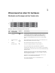
Wissenswertes über Ihr Gehäuse 1 Merkmale und Anzeigen auf der Vorderseite Abbildung 1. Merkmale und Anzeigen auf der Vorderseite Elem ent Anzeige, Taste oder Anschluss Symbol Beschreibung 1 Systemidentifikati onstaste Mit einer Systemidentifizierungstaste auf der Vorderseite kann ein bestimmtes Gehäuse innerhalb eines Racks lokalisiert werden.
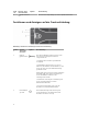
Elem ent Anzeige, Taste oder Anschluss 4 Festplattenlaufwe rke Symbol Beschreibung Bis zu 12 hot-swap-fähige 3,5-Zoll-Festplattenlaufwerke. Funktionen und Anzeigen auf der Frontverkleidung Abbildung 2. Funktionen und Anzeigen auf der Frontverkleidung Elemen Anzeige, t Taste oder Anschluss 1 Symbol LED für Gehäusestatu Abbildung 3. s Beschreibung Die LED für Gehäusestatus leuchtet, wenn die Stromversorgung des Gehäuses eingeschaltet ist. Leuchtet beim normalen Systembetrieb stetig blau.
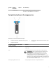
Elemen Anzeige, t Taste oder Anschluss 3 Symbol Freigabehebel Beschreibung Die Verriegelung wird verwendet, um die Blende von dem Gehäuse zu entfernen. Festplattenlaufwerk-Anzeigemuster Abbildung 4. Festplattenlaufwerk-Anzeigen 1. Festplattenlaufwerk-Aktivitätsanzeige (grün) 3. Festplattenlaufwerk 2.
Festplattenlaufwerk– Status-LEDMuster (nur RAID) Zustand Blinkt gelb, viermal pro Sekunde Festplattenlaufwerk fehlgeschlagen Blinkt grün, langsam Neuerstellung des Festplattenlaufwerks Stetig grün Festplattenlaufwerk online Blinkt grün für 3 Sekunden, gelb für 3 Sekunden und schaltet sich für sechs Sekunden aus. Wiederaufbau abgebrochen Merkmale und Anzeigen auf der Rückseite Abbildung 5.
Gehäuseverwaltungsmodul Jedes EMM stellt für das Gehäuse die folgenden Datenpfad- und Gehäuseverwaltungsfunktionen bereit: • Überwachung und Steuerung von Gehäuseumgebungselementen (Temperatur, Lüfter, Netzteile und Gehäuse-LEDs) • Zugriffssteuerung für die Festplattenlaufwerke • Weiterleitung von Gehäuseattributen und -zuständen an den Host-Server ANMERKUNG: Im Gehäuse muss mindestens ein EMM installiert sein.
Beim Ausfall eines EMM-Partners aktiviert der verbleibende EMM die gelbe Status-LED des defekten EMMs. Das verbleibende EMM übernimmt dann die Gehäuseverwaltung, also die Überwachung und Steuerung der Gehäuse-LEDs, der Netzteile und der Lüfter. EMM-Temperaturabschaltung Bei kritischen internen Temperaturwerten wird das Gehäuse automatisch ausgeschaltet, entweder durch einen entsprechenden Befehl von der EMM-Firmware oder einen Befehl vom Dell OpenManage Server Administrator.
Weitere nützliche Informationen WARNUNG: Beachten Sie die Hinweise zu Sicherheit und Betrieb, die mit dem Computer geliefert wurden. Garantieinformationen wurden möglicherweise als separates Dokument beigelegt. • In der zusammen mit der Rack-Lösung gelieferten Rack-Dokumentation ist beschrieben, wie das System in einem Rack installiert wird. • Das Handbuch zum Einstieg enthält eine Übersicht über die Systemfunktionen, die Einrichtung des Systems und technische Daten.
Installation von Gehäusekomponenten Empfohlene Werkzeuge Für die in diesem Abschnitt beschriebenen Maßnahmen benötigen Sie gegebenenfalls die folgenden Werkzeuge: • Schlüssel für das Systemschloss • Kreuzschlitzschraubendreher der Größe 2 • Erdungsband Frontverkleidung (optional) Entfernen der Frontverkleidung 1. Entriegeln Sie gegebenenfalls die Frontverkleidung mit dem Systemschlüssel. 2. Heben Sie die Sperrklinke neben dem Schloss an. 3.
Abbildung 8. Frontverkleidung entfernen und installieren 1. Schloss 2. Frontverkleidung Installieren der Frontverkleidung 1. Haken Sie das rechte Ende der Frontverkleidung am Gehäuse ein. 2. Schwenken Sie das freie Ende der Frontverkleidung auf das System. 3. Sichern Sie die Frontverkleidung mit dem Systemschloss. Festplattenlaufwerke Sicherheit: Modelle AMT, E03J und E04J Die Modelle AMT, E03J und E04J dienen nur der Installation an Orten mit eingeschränktem Zugang entsprechend Klausel 1.2.7.
Entfernen eines Festplattenlaufwerksplatzhalters VORSICHT: Um eine ausreichende Systemkühlung zu gewährleisten, stellen Sie sicher, dass alle leeren Festplattenlaufwerksschächte mit den entsprechenden Platzhaltern belegt sind. 1. Falls installiert, entfernen Sie die Frontverkleidung. Siehe Entfernen der Frontverkleidung. 2. Drücken Sie auf die Freigabelasche und schieben Sie den Festplattenlaufwerkplatzhalter heraus, bis er vollständig aus dem Festplattenlaufwerksschacht entfernt wurde. Abbildung 9.
Wenn das Festplattenlaufwerk online war, blinkt die grüne Aktivitäts- oder Fehler-LED-Anzeige, da die Festplatte ausgeschaltet wird. Wenn die Laufwerksanzeigen erloschen sind, ist das Festplattenlaufwerk zum Ausbau bereit. Weitere Informationen finden Sie unter FestplattenlaufwerkAnzeigemuster. 3. Drücken Sie die Entriegelungstaste, um den Verschlussbügel des Festplattenlaufwerksträgers zu öffnen. 4. Ziehen Sie das Festplattenlaufwerk ganz aus dem Festplattenlaufwerkschacht.
VORSICHT: Stellen Sie beim Installieren von Festplattenlaufwerken sicher, dass die angrenzenden Festplattenlaufwerke vollständig installiert sind. Wenn Sie versuchen, einen Festplattenlaufwerksträger neben einem unvollständig eingesetzten Träger einzusetzen und zu verriegeln, kann die Schirmfeder des nicht fest sitzenden Trägers beschädigt und unbrauchbar gemacht werden. 1. Entfernen Sie gegebenenfalls die Frontverkleidung. Siehe Entfernen der Frontverkleidung. 2.
Installieren eines Festplattenlaufwerks in einem Festplattenlaufwerkträger 1. Führen Sie das Festplattenlaufwerk in den Festplattenlaufwerkträger ein, wobei sich das Anschlussende des Festplattenlaufwerks hinten befindet. 2. Richten Sie die Schraublöcher in dem Festplattenlaufwerk mit den hinteren Löchern am Festplattenlaufwerkträger aus. Bei korrekter Ausrichtung schließt die Rückseite des Festplattenlaufwerks mit der Rückseite des Festplattenlaufwerkträgers ab. 3.
Abbildung 12. Entfernen und Installieren einer EMM-Platzhalterkarte 1. EMM-Platzhalterkarte 2. Sperrklinke Installieren einer EMM-Platzhalterkarte Um eine EMM-Platzhalterkarte zu installieren, richten Sie die Platzhalterkarte auf den EMM-Schacht aus und führen Sie die Platzhalterkarte in das Gehäuse ein, bis sie hörbar einrastet. Entfernen eines EMM VORSICHT: Viele Reparaturen am Computer dürfen nur von einem zertifizierten Servicetechniker ausgeführt werden.
Abbildung 13. EMM entfernen und installieren 1. Freigabehebel 3. Freigabelasche 2. EMM Installieren eines EMMs VORSICHT: Viele Reparaturen am Computer dürfen nur von einem zertifizierten Servicetechniker ausgeführt werden. Sie sollten nur die Behebung von Störungen sowie einfache Reparaturen unter Berücksichtigung der jeweiligen Angaben in den Produktdokumentationen von Dell durchführen, bzw. die elektronischen oder telefonischen Anweisungen des Service- und Supportteams von Dell befolgen.
Wechselstrom-Netzteil oder Lüftermodul Das Gehäuse unterstützt zwei hot-swap-fähige Netzteile oder Lüftermodule. Obwohl das Gehäuse kurzzeitig mit nur einem Modul betrieben werden kann, müssen beide Kühlmodule im Dauerbetrieb vorhanden sein. VORSICHT: Ein einzelnes Netzteil oder Lüftermodul kann für maximal fünf Minuten aus einem eingeschalteten Array entfernt werden. Wird diese Zeit überschritten, kann es zur automatischen Abschaltung des Arrays kommen, um Schäden zu verhindern.
Installieren eines Wechselstrom-Netzteils oder Lüftermoduls 1. Schieben Sie das Netzteil oder das Lüftermodul in das Gehäuse, bis die Sperrklinke einrastet. 2. Verbinden Sie das Stromversorgungskabel mit dem Netzteil oder Lüftermodul und schließen Sie das Kabel an einer Steckdose an. 3. Befestigen Sie das Stromversorgungskabel mit dem Klettstreifen. Abbildung 15. Befestigen der Stromkabel 1. Klettstreifen VORSICHT: Wenn Sie das Netzstromkabel anschließen, sichern Sie dieses mit dem Klettband.
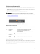
Abbildung 16. Betriebsanzeigecodes Eleme nt LED Farbe 1 Leistungsa Grün bgabe Zustand • • EIN - Normaler Betrieb. Das Netzteil ist mit dem Gleichstromnetz verbunden und der Netzschalter ist eingeschaltet. Das Netzteilmodul versorgt das Array mit Gleichstrom. AUS - Kann folgende Bedeutungen haben: – Der Netzschalter ist ausgeschaltet. – Das Netzteilmodul ist nicht an die Stromversorgung angeschlossen. – Es ist eine Störung aufgetreten.
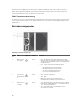
Rückseitenmerkmale eines Gleichstrom-Netzteilmoduls Abbildung 17. Rückseitenmerkmale eines Gleichstrom-Netzteilmoduls Elemen Funktion t Beschreibung 1 NetzteilEntriegelungshebel Entriegelt das Netzteilmodul, um es aus dem Speicher-Array zu entfernen. 2 Steckverbindung auf dem Netzteilmodul Verbindet das Netzteilmodul mit dem Gleichstrom-Netzteilmodul. 3 EIN/AUS-Schalter des Netzteils Steuert die Leistungsabgabe vom Netzteilmodul zum Speicher-Array.
Erforderliche Kabel • Ein schwarzer, maximal 2 m langer (verdrillter) UL-10-AWG-Leiter [–(48–60) V Gleichspannung] • Ein roter, maximal 2 m langer (verdrillter) UL-10-AWG-Leiter (Gleichstrom-Rückleiter) • Ein (verlitzter) AWG-Draht der Stärke 10 vom Typ UL, grün/gelb/grün mit einem gelben Streifen, maximal 2 m lang (Schutzerdung) Schutzerdungskabel montieren und anschließen WARNUNG: Bei Geräten, die -(48-60) V-Gleichstrom-Netzteile verwenden, muss ein qualifizierter Elektriker alle Verbindungen zum Gl
Verkabelung der Stromversorgungskabel WARNUNG: Bei Geräten, die -(48-60) V-Gleichstrom-Netzteile verwenden, muss ein qualifizierter Elektriker alle Verbindungen zum Gleichstrom und zu Sicherheitsanlagen herstellen. Versuchen Sie nicht, die Verbindung zum Gleichstrom und zu Sicherheitsanlagen selbst herzustellen. Alle elektrischen Verkabelungen müssen den zutreffenden lokalen oder nationalen Regeln und Verfahren entsprechen.
3. Bringen Sie die Stromversorgungskabel am Netzteilmodul an, indem Sie die Stromversorgungskabel mithilfe der beigefügten (angebauten) Fingerschrauben sicher am System befestigen. 4. Richten Sie die Schrauben auf die entsprechenden Schraubenbohrungen am System aus und ziehen Sie sie an, bis der Stromversorgungsstecker sicher befestigt ist. Abbildung 20. Anschließen der Gleichstromkabel 1. angefügte (unverlierbare) Handschrauben 3. Steckverbindung am Netzteilmodul 2.
4. Trennen Sie den Schutzerdungsleiter. 5. Drücken Sie auf die Freigabevorrichtung und schieben Sie das Netzteil aus dem Gehäuse. VORSICHT: Das Netzteilmodul ist schwer. Halten Sie es mit beiden Händen fest. Abbildung 21. Entfernen und Installieren eines Gleichstrom-Netzteilmoduls 1. Sperrklinke 3. Netzteilmodulgriff 2.
4. Verbinden Sie den Schutzerdungsleiter. 5. Installieren Sie den Gleichstromanschluss in das Netzteil. VORSICHT: Wenn Sie die Stromdrähte verbinden, befestigen Sie die Drähte mit dem Band am Netzteilmodulgriff. 6. Schließen Sie die Drähte an eine Gleichstromquelle an. ANMERKUNG: Die Netzanschluss-LED leuchtet auf, wenn das Netzkabel angeschlossen wird, auch wenn die Netzschalter der Netzteilmodule ausgeschaltet sind. ANMERKUNG: Wenn Sie ein neues Netzteil einbauen bzw.
3. • Schließen Sie ein anderes Gerät an die Stromquelle an, um zu überprüfen, ob die Stromquelle korrekt funktioniert. • Schließen Sie das Kabel an eine andere Stromquelle an. • Ersetzen Sie das Stromversorgungskabel. Setzen Sie die Netzteile neu ein, indem Sie sie entfernen und neu installieren. Weitere Informationen hierzu finden Sie unter Entfernen eines Gleichstrom-Netzteils und Installieren eines Gleichstrom-Netzteils. Wenn das Problem nicht behoben wurde, lesen Sie Wie Sie Hilfe bekommen.
Entfernen des Bedienfelds 1. Schalten Sie das Gehäuse und den Host-Server aus. 2. Trennen Sie alle Stromkabel vom Gehäuse. 3. Entfernen Sie die Festplattenlaufwerke in Steckplatz 0 und 2. Weitere Hinweise finden Sie unter Entfernen eines Festplattenlaufwerks. 4. Schieben Sie das Bedienfeld aus dem Gehäuse heraus, nachdem Sie die Freigabelasche in Richtung der Vorderseite des Gehäuses gedrückt haben. Abbildung 22. Bedienfeldplatine entfernen und installieren 1. Bedienfeld 3. Freigabelasche 2.
Rückwandplatine WARNUNG: Beim Anheben des Systems sollten Sie sich stets von anderen helfen lassen. Um Verletzungen zu vermeiden, sollten Sie nicht versuchen, das System allein zu bewegen. VORSICHT: Viele Reparaturen am Computer dürfen nur von einem zertifizierten Servicetechniker ausgeführt werden. Sie sollten nur die Behebung von Störungen sowie einfache Reparaturen unter Berücksichtigung der jeweiligen Angaben in den Produktdokumentationen von Dell durchführen, bzw.
Abbildung 23. Entfernen und Installieren des EMM oder Netzteilgehäuses 1. 9. EMM oder Netzteilgehäuse 2. Schrauben (6) Heben Sie das EMM oder Netzteilgehäuse aus dem Gehäuse. 10. Lösen Sie die unverlierbare Schraube, mit der die Rückwandplatine am Gehäuse befestigt ist. 11. Entfernen Sie die Schrauben, mit denen die Rückwandplatine befestigt ist, und ziehen Sie die Rückwandplatine aus dem Gehäuse. Abbildung 24. Rückwandplatine entfernen und installieren 32 1. Schrauben (5) 3. Rückwandplatine 2.
Installieren der Rückwandplatine 1. Richten Sie die Löcher der Rückwandplatine auf die Löcher im Gehäuse aus. 2. Befestigen Sie die unverlierbare Schraube, die das Netzteil am Gehäuse sichert. 3. Bringen Sie die Schrauben wieder an, mit denen die Rückwandplatine am Gehäuse befestigt wird. 4. Richten Sie die Schlitze am EMM oder Netzteilgehäuse auf die Laschen am Gehäuse aus. 5. Drücken Sie das EMM oder Netzteilgehäuse in Richtung der Gehäusevorderseite. 6.
Fehlerbehebung am Gehäuse 3 Sicherheit geht vor – für Sie und das Gehäuse VORSICHT: Viele Reparaturen am Computer dürfen nur von einem zertifizierten Servicetechniker ausgeführt werden. Sie sollten nur die Behebung von Störungen sowie einfache Reparaturen unter Berücksichtigung der jeweiligen Angaben in den Produktdokumentationen von Dell durchführen, bzw. die elektronischen oder telefonischen Anweisungen des Service- und Supportteams von Dell befolgen.
Fehlerbehebung beim Stromversorgungs- oder Lüftermodul VORSICHT: Viele Reparaturen am Computer dürfen nur von einem zertifizierten Servicetechniker ausgeführt werden. Sie sollten nur die Behebung von Störungen sowie einfache Reparaturen unter Berücksichtigung der jeweiligen Angaben in den Produktdokumentationen von Dell durchführen, bzw. die elektronischen oder telefonischen Anweisungen des Service- und Supportteams von Dell befolgen.
Fehlerbehebung bei Problemen mit der Gehäusekühlung VORSICHT: Viele Reparaturen am Computer dürfen nur von einem zertifizierten Servicetechniker ausgeführt werden. Sie sollten nur die Behebung von Störungen sowie einfache Reparaturen unter Berücksichtigung der jeweiligen Angaben in den Produktdokumentationen von Dell durchführen, bzw. die elektronischen oder telefonischen Anweisungen des Service- und Supportteams von Dell befolgen.
– Lösen Sie die Verbindungskabel von Speichergehäuse und Server und schließen Sie sie erneut an. – Starten Sie das Speichergehäuse wieder und warten Sie, bis das Gehäuse vollständig gestartet ist. – Schalten Sie den Server ein. – Überprüfen Sie die Verbindungsstatus-LED. Sollte die Verbindungsstatus-LED nicht grün leuchten, fahren Sie mit dem nächsten Schritt fort. Wenn das Problem nicht behoben wurde, lesen Sie Wie Sie Hilfe bekommen.
ANMERKUNG: Sie müssen den Host-Server ausschalten, bevor Sie Kabel kurzzeitig vom Gehäuse trennen und wieder anschließen. Wenn das Problem nicht behoben wurde, lesen Sie Wie Sie Hilfe bekommen. Fehlerbehebung bei Feuchtigkeit im Gehäuse VORSICHT: Viele Reparaturen am Computer dürfen nur von einem zertifizierten Servicetechniker ausgeführt werden.
Wie Sie Hilfe bekommen 4 Kontaktaufnahme mit Dell ANMERKUNG: Dell bietet verschiedene Optionen für Online- und Telefonsupport an. Wenn Sie über keine aktive Internetverbindung verfügen, so finden Sie Kontaktinformationen auf der Eingangsrechnung, dem Lieferschein, der Rechnung oder im Dell Produktkatalog. Die Verfügbarkeit ist abhängig von Land und Produkt und einige Dienste sind in Ihrem Gebiet möglicherweise nicht verfügbar.