
Owners Manual
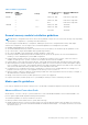


Table Of Contents
- Dell PowerEdge R730 Owner's Manual
- Contents
- Dell PowerEdge R730 system overview
- Documentation resources
- Technical specifications
- Initial system setup and configuration
- Pre-operating system management applications
- Options to manage the pre-operating system applications
- System Setup
- Viewing System Setup
- System Setup details
- System BIOS
- iDRAC Settings utility
- Device Settings
- Dell Lifecycle Controller
- Boot Manager
- PXE boot
- Installing and removing system components
- Safety instructions
- Before working inside your system
- After working inside your system
- Recommended tools
- Front bezel (optional)
- System cover
- Inside the system
- Cooling shroud
- Cooling fans
- Cooling fan assembly
- System memory
- Processors and heat sinks
- PCIe card holder
- Cable retention bracket
- Integrated storage controller card
- Expansion cards and expansion card riser
- Expansion card installation guidelines
- Removing an expansion card from expansion card riser 2 or 3
- Installing an expansion card into the expansion card riser 2 or 3
- Removing an expansion card from the expansion card riser 1
- Installing an expansion card into the expansion card riser 1
- Removing the riser 1 blank
- Installing the riser 1 blank
- Removing expansion card risers
- Installing expansion card risers
- GPU card installation guidelines
- Removing the GPU card
- Installing a GPU card
- IDSDM
- Network daughter card
- Internal USB memory key (optional)
- System battery
- Power supply units (PSU)
- System board
- Trusted Platform Module
- Hard drives
- Removing a 2.5-inch hard drive blank
- Installing a 2.5-inch hard drive blank
- Removing a 3.5-inch hard drive blank
- Installing a 3.5-inch hard drive blank
- Removing a hot swappable hard drive or solid state drive
- Installing a hot swappable hard drive or solid state drive
- Removing a hard drive or a solid state drive from a hard drive carrier
- Installing a hard drive or solid state drives into a hard drive carrier
- Removing a 1.8-inch hard drive blank
- Installing a 1.8-inch hard drive blank
- Removing a 1.8-inch hard drive from a hard drive carrier
- Installing a 1.8-inch hard drive into a hard drive carrier
- Hard drive backplane
- Tape backup unit (optional)
- Optical drive (optional)
- SD vFlash card (optional)
- Control panel assembly
- Using system diagnostics
- Jumpers and connectors
- Troubleshooting your system
- Troubleshooting system startup failure
- Troubleshooting external connections
- Troubleshooting the video subsystem
- Troubleshooting a USB device
- Troubleshooting iDRAC Direct - USB XML configuration
- Troubleshooting iDRAC Direct - Laptop connection
- Troubleshooting a serial input and output device
- Troubleshooting a NIC
- Troubleshooting a wet system
- Troubleshooting a damaged system
- Troubleshooting the system battery
- Troubleshooting power supply units
- Troubleshooting cooling problems
- Troubleshooting cooling fans
- Troubleshooting system memory
- Troubleshooting an internal USB key
- Troubleshooting a micro SD card
- Troubleshooting an optical drive
- Troubleshooting a tape backup unit
- Troubleshooting a drive or SSD
- Troubleshooting a storage controller
- Troubleshooting expansion cards
- Troubleshooting processors
- System messages
- Getting help

Table 36. Memory population
DIMM Type DIMMs
Populated/
Channel
Voltage
Operating Frequency
(in MT/s)
Maximum DIMM Rank/
Channel
RDIMM 1
1.2 V
2400, 2133, 1866 Dual rank or single rank
2 2400, 2133, 1866 Dual rank or single rank
3 1866 Dual rank or single rank
LRDIMM 1
1.2 V
2400, 2133, 1866 Quad rank
2 2400, 2133, 1866 Quad rank
3 2133, 1866 Quad rank
General memory module installation guidelines
NOTE: Memory configurations that fail to observe these guidelines can prevent your system from booting, stop responding
during memory configuration, or operating with reduced memory.
The system supports Flexible Memory Configuration, enabling the system to be configured and run in any valid chipset
architectural configuration. The following are the recommended guidelines for installing memory modules:
● RDIMMs and LRDIMMs must not be mixed.
● x4 and x8 DRAM based memory modules can be mixed. For more information, see the Mode-specific guidelines section.
● Up to three dual- or single-rank RDIMMs can be populated per channel.
● Up to three LRDIMMs can be populated per channel regardless of rank count.
● If memory modules with different speeds are installed, they will operate at the speed of the slowest installed memory
module(s) or slower depending on system DIMM configuration.
● Populate memory module sockets only if a processor is installed. For single-processor systems, sockets A1 to A12 are
available. For dual-processor systems, sockets A1 to A12 and sockets B1 to B12 are available.
● Populate all the sockets with white release tabs first, followed by the black release tabs, and then the green release tabs.
● When mixing memory modules with different capacities, populate the sockets with memory modules with highest capacity
first. For example, if you want to mix 4 GB and 8 GB memory modules, populate 8 GB memory modules in the sockets with
white release tabs and 4 GB memory modules in the sockets with black release tabs.
● In a dual-processor configuration, the memory configuration for each processor should be identical. For example, if you
populate socket A1 for processor 1, then populate socket B1 for processor 2, and so on.
● Memory modules of different capacities can be mixed provided other memory population rules are followed (for example, 4
GB and 8 GB memory modules can be mixed).
● Mixing of more than two memory module capacities in a system is not supported.
● Populate four memory modules per processor (one DIMM per channel) at a time to maximize performance.
Mode-specific guidelines
Four memory channels are allocated to each processor. The allowable configurations depend on the memory mode selected.
Advanced Error Correction Code
Advanced Error Correction Code (ECC) mode extends SDDC from x4 DRAM based DIMMs to both x4 and x8 DRAMs. This
protects against single DRAM chip failures during normal operation.
The installation guidelines for memory modules are as follows:
● Memory modules must be identical in size, speed, and technology.
● DIMMs installed in memory sockets with white release levers must be identical and the same rule applies for sockets with
black release levers. This ensures that identical DIMMs are installed in matched pair —for example, A1 with A2, A3 with A4,
A5 with A6, and so on.
Installing and removing system components
81