
Owners Manual


CAUTION: When connecting the power wires, ensure that you secure the wires with the strap to the PSU
handle.
4. Connect the wires to a DC power source.
NOTE: When installing, hot-swapping, or hot-adding a new PSU, wait for 15 seconds for the system to recognize the
PSU and determine its status. The PSU status indicator turns green to signify that the PSU is functioning properly.
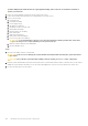
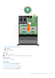
Figure 80. Installing a DC PSU
1.
release latch 2. power supply status indicator
3. PSU 4. power connector
5. PSU handle
Next steps
● Follow the procedure listed in the After working inside your system section.
System board
A system board (also known as the motherboard) is the main printed circuit board in the system with different connectors used
to connect different components or peripherals of the system. A system board provides the electrical connections to the
components in the system to communicate.
Removing the system board
Prerequisites
CAUTION:
Many repairs may only be done by a certified service technician. You should only perform
troubleshooting and simple repairs as authorized in your product documentation, or as directed by the online or
telephone service and support team. Damage due to servicing that is not authorized by Dell is not covered by
your warranty. Read and follow the safety instructions that are shipped with your product.
CAUTION: If you are using the Trusted Platform Module (TPM) with an encryption key, you may be prompted to
create a recovery key during program or System Setup. Be sure to create and safely store this recovery key. If
you replace this system board, you must supply the recovery key when you restart your system or program
before you can access the encrypted data on your hard drives.
CAUTION: Do not attempt to remove the TPM plug-in module from the system board. Once the TPM plug-in
module is installed, it is cryptographically bound to that specific system board. Any attempt to remove an
Installing and removing system components 141