Dell Lifecycle Controller GUI v2.40.40.
Notes, cautions, and warnings NOTE: A NOTE indicates important information that helps you make better use of your product. CAUTION: A CAUTION indicates either potential damage to hardware or loss of data and tells you how to avoid the problem. WARNING: A WARNING indicates a potential for property damage, personal injury, or death. © 2016 Dell Inc. All rights reserved. This product is protected by U.S. and international copyright and intellectual property laws.
Contents 1 Introduction..................................................................................................................... 7 Why use Lifecycle Controller?............................................................................................................................................ 7 Benefits of using iDRAC with Lifecycle Controller.............................................................................................................. 7 What's new in this release?........
Viewing or exporting hardware inventory after part replacement.................................................................................... 29 Viewing or exporting current inventory after resetting Lifecycle Controller..................................................................... 29 Lifecycle Controller log.....................................................................................................................................................29 Viewing Lifecycle Log history.........
FTP authentication.................................................................................................................................................... 55 Requirements for a local FTP server.......................................................................................................................... 56 Copying repository to a local FTP server from the Dell Server Updates DVD.............................................................
System BIOS screen...................................................................................................................................................77 System information screen......................................................................................................................................... 77 Memory Settings screen............................................................................................................................................
1 Introduction Dell Lifecycle Controller provides advanced embedded systems management to perform systems management tasks such as deploy, configure, update, maintain, and diagnose using a graphical user interface (GUI). It is delivered as part of integrated Dell Remote Access Controller (iDRAC) out-of-band solution and embedded Unified Extensible Firmware Interface (UEFI) applications in the latest Dell servers.
For more information on iDRAC, see the Integrated Dell Remote Access Controller User’s Guide at dell.com/support/home. For more information on wsman, see the Dell Lifecycle Controller GUI User’s Guide at delltechcenter.com/lc. What's new in this release? The updates supported in this release are: • Added support for the Windows 2016 and the Red Hat Enterprise Linux 6.8 operating systems. • Added support to export and import of Server Configuration Profiles using Redfish interface.
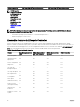
Feature matrix The following table lists the Lifecycle Controller features supported on the 12th and 13th generation Dell PowerEdge servers. Table 1.
Dell PowerEdge 12th generation servers Features supported Dell PowerEdge 13th generation servers NOTE: Specific component selection is not supported on the Dell's 12th generation of PowerEdge servers. For more information on this feature, see Repurpose or retire system. NOTE: The following features are supported on the 12th generation PowerEdge servers only if iDRAC and Lifecycle Controller versions are 2.10.10.
Viewing iDRAC license information After you open the Lifecycle Controller GUI page, you can view details about the iDRAC installed on a server. To view the iDRAC license information: 1. Start Lifecycle Controller. For more information, see Starting Lifecycle Controller. 2. On any page of Lifecycle Controller, click About in the upper-right corner. 3. On the About page, click License Information. The following information is displayed on the iDRAC License Report page: Table 3.
• The Rack Installation Instructions included with your rack solution describe how to install your system into a rack. • The Getting Started Guide provides an overview of system features, setting up your system, and technical specifications. • The Owner’s Manual provides information about system features and describes how to troubleshoot the system and install or replace system components. • Lifecycle Controller Web Services Interface Guide–Windows and Linux.
4. Select the appropriate service or support link based on your need.
2 Using Lifecycle Controller This section provides information about starting, enabling, and disabling Lifecycle Controller. Before using Lifecycle Controller, make sure that the network and iDRAC are configured. For more information, see the Integrated Dell Remote Access Controller User’s Guide at dell.com/esmmanuals. Starting Lifecycle Controller To start Lifecycle Controller, restart the system and press during POST to select Lifecycle Controller from the list displayed.
Message Cause Resolution – 3 consecutive unsuccessful attempts to perform tasks in Automated Task applications. Lifecycle Controller not available Another process is using iDRAC. Wait for 30 minutes for the current process to complete, restart the system, and then retry. You can use the iDRAC GUI to check the job queue and the status. Related links Disabling Lifecycle Controller Enabling Lifecycle Controller To enable access to Lifecycle Controller during system startup: 1. Press during POST.
4. Under Cancel Lifecycle Controller Actions, select Yes. 5. On the System Setup Main Menu page, select Finish to save the settings. 6. Select Yes to restart the system. Using Lifecycle Controller for the first time After you start Lifecycle Controller for the first time, by default the Initial Setup Wizard page is launched. Use this wizard to set up the Language ,Keyboard Type, Network Settings, and iDRAC Network and Credentials.
NOTE: While configuring DHCP server with IPv6, the configuration fails if you disable forwarding or advertising options. • 7. Static IP — indicates that the NIC must be configured using a static IP. Type the IP Address Properties — IP Address, Subnet Mask, Default Gateway, and DNS Address. If you do not have this information, contact your network administrator. Click Enabled and type the VLAN ID and Priority under Lifecycle Controller VLAN Settings to configure the VLAN settings of a NIC.
Characters Length -!#$%&()*/;?@[\]^_`{|}~+<=> Table 6. Recommended characters for passwords Characters Length 0-9 A-Z a-z '-!"#$%&()*,./:;?@[\]^_`{|}~+<=> 1-20 NOTE: You may be able to create user names and passwords that include other characters. However, to ensure compatibility with all interfaces, Dell recommends using only the characters listed here.
Configuring Lifecycle Controller Network Settings Use this page to configure network settings for a NIC. 1. Start Lifecycle Controller. For more information, see Starting Lifecycle Controller. 2. On the left pane, click Settings. 3. On the Settings pane, click Network Settings. 4. From the NIC Card drop-down menu, select the NIC port that you want to configure. NOTE: You can use only one NIC at a time to communicate with the network. 5.
• Lifecycle Log — View and export the Lifecycle Controller log, and add a work note to the log. • Firmware Update — Apply updates or perform firmware rollback for the system components, and view the firmware version available on a server. • Hardware Configuration — Configure system devices, view, export hardware inventory of a system, and repurpose or retire system. • OS Deployment — Install an operating system in manual mode or unattended mode by using an 'answer' file.
3 Operating system deployment The OS Deployment feature allows you to deploy standard and custom operating systems on the managed system. You can also configure RAID before installing the operating system if it is not already configured. Lifecycle Controller allows deploying the operating system using the following options: • Manual installation • Unattended installation. For more information on unattended installation, see Unattended installation. • UEFI Secure Boot.
NOTE: The Secure Boot option is available only if the Load Legacy Video Option ROM setting is set to disabled. To disable the Load Legacy Video Option ROM setting, click System Setup → System BIOS Settings → Miscellaneous Settings → Load Legacy Video Option ROM → Disabled. • Secure Boot Policy — Displays the current setting of the boot policy in the BIOS. NOTE: You can change the Secure Boot Policy setting only in BIOS.
Alternatively, you can configure RAID through the RAID configuration page from the Hardware Configuration → Configuration Wizards → RAID Configuration. Configuring RAID using the operating system deployment wizard To configure RAID using the OS Deployment page: NOTE: If the system has a RAID controller, you can configure a virtual disk as the boot device. Create boot virtual disk only from disk drives populated across 0–3 of the system. For slot information, see the system Owner’s Manual at dell.
There are two BIOS attributes that are associated with Secure Boot: • Secure Boot — Displays if the Secure Boot is enabled or disabled. • Secure Boot Policy — Allows you to specify the policy or digital signature that BIOS uses to authenticate. The policy can be classified as: – Standard — BIOS uses the default set of certificates to validate the drivers and operating system loaders during the boot process.
Scenario User Action and Impact During the 18-hour period when drivers are extracted to a temporary location after the operating system is installed, you cannot update the component firmware using a DUP. If you attempt a DUP through the operating system during this time period, the DUP displays a message that another session is active. Lifecycle Controller does not allow DUP after the operating system installation.
4 Monitor Using Lifecycle Controller, you can monitor the hardware inventory and events of a server throughout its life cycle.
To view the currently installed or factory-installed hardware components and their configuration details: 1. Start Lifecycle Controller. For more information, see Starting Lifecycle Controller. 2. In the left pane, click Hardware Configuration. 3. In the right pane, click Hardware Inventory. 4. To view the current- or factory-shipped inventory, click View Current Inventory or View Factory Shipped Inventory respectively.
Related links About view and export current inventory About view and export factory-shipped inventory Exporting hardware inventory to a USB drive Exporting hardware inventory to a network share Exporting hardware inventory to a USB drive To export hardware-related inventory to a USB drive: 1. From the Select Device drop-down menu, select a USB drive. 2. In the File Path box, type a valid directory or subdirectory path on the device. For example, 2015\Nov.
Viewing or exporting hardware inventory after part replacement To view or export the hardware inventory after part replacement: 1. Start Lifecycle Controller. For more information, see Starting Lifecycle Controller. 2. In the left pane, click Hardware Configuration. 3. In the right pane, click Hardware Inventory. 4. Click View Current Inventory. Lifecycle Controller displays the old hardware inventory. 5. Restart the server and relaunch Lifecycle Controller. 6.
NOTE: If you initiate configuration jobs using RACADM CLI or iDRAC web interface, the Lifecycle log displays information about the user, interface used, and the IP address of the system from which you initiate the job.
Exporting Lifecycle Log Use the Export Lifecycle Log feature to export the Lifecycle Log information to a compressed file (.gz format) that has log files in an .xml file. You can save the XML file in a USB drive or on a network share. For more information about the schema, see en.community.dell.com/techcenter/extras/m/white_papers/20270305.
• File Path — Type the sub-directories, if any. For example, 2015\Nov. NOTE: The following characters are supported for user name and password: – Digits (0–9) – Alphabets (a-z, A-Z) – Hyphen (-) NOTE: Lifecycle Controller allows 256 characters in a path that includes the file name and file extension. For example, if 56 characters are used for file name and extension, only 200 characters can be used for the path. Lifecycle Controller does not support these characters -:, *,?,”,<,>,|,#,%,^, and SPACE.
5 Firmware update Using Lifecycle Controller, the system can be updated using the repositories accessible through FTP or on a locally attached USB drive, DVD, or network share. Use the Firmware Update page to: • View the current version of the installed applications and firmware. • View a list of available updates. • Select the required updates, downloads (automatic), and then apply the updates to the following components listed in the table.
Related links Firmware update methods Version compatibility Updating firmware Firmware update methods The following table lists the various locations or media and methods to perform the updates: NOTE: If the FTP server or network share is used for updates, configure the network card using the Settings wizard before accessing the updates. Table 10.
Version compatibility The version compatibility feature enables you to update the component firmware versions that are compatible with system components. In case of compatibility issues, Lifecycle Controller displays upgrade or downgrade error messages during the update. Updating firmware You can update to the latest version of Lifecycle Controller using the Firmware Update wizard. It is recommended that you run the Firmware Update wizard regularly to access the latest updates.
NOTE: The system does not restart if operating system driver packs, OS collector tool, or hardware diagnostics are updated. NOTE: When applying more than one update, the system may restart between updates. In this case, Lifecycle Controller restarts the server and automatically continues the update process. NOTE: iDRAC resets while updating iDRAC. If the iDRAC firmware update is interrupted for any reason, wait for up to 30 minutes before you attempt another firmware update.
Using a DVD Use either the Server Update Utility (SUU) DVDs or custom DVDs (SUU ISO downloaded from dell.com/support and written to a DVD) to perform the firmware updates. The available DVDs are: • OpenManage SUU DVD to update all the server components such as Lifecycle Controller, Dell Diagnostics, BIOS, RAID controller, NIC, iDRAC, and Power Supply Unit. • Lifecycle Controller OS Driver Packs DVD (Windows only) to update the operating system driver packs. To access the updates from a DVD: 1.
Related links Accessing updates on a local FTP server Configuring a local USB drive Using a non-proxy FTP server Lifecycle Controller can access the latest firmware from ftp.dell.com. It downloads the DUPs from this location to perform firmware update. Before performing an update using a non-proxy FTP server, make sure that the following prerequisites are met: • The network settings are configured (Settings → Network Settings).
NOTE: Lifecycle Controller allows 256 characters in a path that includes the file name and file extension. For example, if 56 characters are used for file name and extension, only 200 characters can be used for the path. Lifecycle Controller does not support these characters -:, *,?,”,<,>,|,#,%,^, and SPACE. • Enable Settings — Select this option to enter the following details: – Server — The host name of the proxy server. – Port — The port number of the proxy server.
Using single component DUPs To use single component Dell Update Packages (DUP), download the Dell Update Package (only .exe) from the Dell FTP site (ftp.dell.com), or copy from the Server Update Utility DVD, or from dell.com/support to a local hard disk drive or network share. NOTE: Make sure that the file name for the single component DUPs does not have any blank space. NOTE: Both 32–bit and 64–bit DUPs are supported.
• The earlier version of the firmware is available only if any of the following tools are used to update the firmware: Lifecycle Controller Firmware Update feature, Lifecycle Controller-Remote Services, or the Dell Update Package (DUP) from operating system. NOTE: You cannot roll back to firmware version 1.x.x or earlier on a 13th generation PowerEdge server.
6 Configure Lifecycle Controller provides various system configuration wizards. Use the configuration wizards to configure system devices. The Configuration Wizards has: • System Configuration Wizards — This wizard includes LCD Panel Security, iDRAC Settings, System Date and Time Configuration, and vFlash SD card Configuration. • Storage Configuration Wizards — This wizard includes RAID Configuration, Key Encryption, and Break Mirror.
Configuring iDRAC To configure iDRAC parameters applicable to the system, such as LAN, common IP settings, IPv4, IPv6, Virtual Media, and LAN user configuration use the iDRAC Settings wizard. NOTE: You can also use the System Setup utility during startup for configuring iDRAC. For more information about the System Setup utility, see Using The System Setup Program And Boot Manager. To configure and manage the iDRAC parameters: 1. Start Lifecycle Controller.
NOTE: The options under vFlash SD card are grayed-out if there is no SD card inserted in the slot. NOTE: If FIPS is enabled, you cannot perform any actions associated with the vFlash SD card, such as configuring the vFlash SD card, exporting or backing up server profile to the vFlash, or importing server profile using vFlash. See the Integrated Dell Remote Access Controller (iDRAC) User’s Guide available at dell.com/support/home for more information on vFlash SD card and the installation procedure.
To configure RAID: 1. Start Lifecycle Controller. For more information, see Starting Lifecycle Controller. 2. In the left pane, click Hardware Configuration. 3. In the right pane, click Configuration Wizards. 4. Under Storage Configuration Wizards, click RAID Configuration to launch the wizard. The View Current RAID Configuration and Select Controller page is displayed. 5. Select the controller and click Next. The Select RAID Level page is displayed. 6. Select the RAID level and click Next.
NOTE: RAID 0 does not provide data redundancy and hot spare. Other RAID levels provide data redundancy and enable you to reconstruct data in the event of a disk-drive failure. NOTE: You can create only one virtual disk using Lifecycle Controller. To create multiple virtual disks, use Option ROM. To access Option ROM, press during boot or POST. Selecting a RAID controller The View Current RAID Configuration and Select Controller page displays all supported RAID controllers attached to the system.
The number of physical disks required for the virtual disk varies depending on the RAID level. The minimum and maximum numbers of physical disks required for the RAID level are displayed on the screen. • Protocol — Select the protocol for the disk pool: Serial Attached SCSI (SAS) or Serial ATA (SATA). SAS drives are used for high performance, while SATA drives provide a more cost-effective solution.
– Force Write Back — The write cache is enabled regardless of whether the controller has an operational battery. If the controller does not have an operational battery, data loss may occur in the event of a power failure. • Disk Cache Policy— Select the write policy. – Enabled — The controller enables physical disk cache setting while creating virtual disks. – Disabled —The controller disables physical disk cache setting while creating virtual disks.
NOTE: During initialization, all the data on the non-RAID disk drives are deleted. 6. Select the RAID level and click Next. The Select Physical Disks page is displayed. 7. Select the physical disk properties and click Next. 8. Select the virtual disk parameters and click Next. The Virtual Disk Attributes page is displayed. The Summary page is displayed. 9. To apply the RAID configuration, click Finish.
Related links Selecting a RAID controller Foreign configuration found Selecting RAID levels Selecting physical disks Setting virtual disk attributes Viewing summary Applying the local key on a RAID controller Key encryption Use the Key Encryption feature to: • Apply local encryption for PERC H710, H710P, H730, H730P, H810, and H830 RAID controllers. • Delete the local encryption key. • Encrypt the existing unsecure virtual drives. • To change an existing encryption key to another one.
• Remove encryption and delete data — Delete the encryption key on the controller and all the secure virtual drives along with its data. After deletion, controller state changes to No encryption mode. Related links Encrypting unsecure virtual disks Rekey controller with new local key Removing encryption and deleting data Encrypting unsecure virtual disks Make sure that the following prerequisites are met: • Selected controller is security-capable.
CAUTION: The existing encryption, virtual drives, and all the data are permanently deleted. 1. Start Lifecycle Controller. For more information, see Starting Lifecycle Controller. 2. In the left pane, click Hardware Configuration. 3. In the right pane, click Configuration Wizards and click Key Encryption. 4. Select the controller on which you must remove the key that was applied and click Next. 5. In the right pane, select Remove encryption and delete data and click Next. 6.
– BCM57710 10GBase-T Single Port NIC – BCM57710 10GBase-T Dual Port Rack Mezzanine Card – BCM57710 Dual Port KX4 Blade Mezzanine Card – BCM57711 Dual Port KX4 Noble MC – BCM95708C PCI-E NIC – BCM95709C 10/100/1000BASET Quad Port NIC – BCM95709 iSCSI Offload Dual Port NIC – BCM957711 10G SFP+ Dual Port NIC – Broadcom 57810S DP 10G SFP+ Adapter (Full Height) – Broadcom 57810S DP 10G SFP+ Adapter (Low Profile) – Broadcom 57800S DP 10G BASE-T Adapter (Full Height) – Broadcom 57800S DP 10G BASE-T Adapter (Low Pr
* QLogic 57810S Dual 10GE PCIe Standup SFP+/DA CNA * QLogic 57810S-k Dual Port 10Gb bMezz KR CNA * QLogic 57840S-K Quad Port 10Gb bNDC KR CNA * QLogic 57840S Quad Port 10GB rNDC SFP+/DA * QLogic Gigabit Network Adapter * QLogic Gigabit Network Adapter (PowerVault) * QLogic QLE2660 Single Port FC16 HBA * QLogic QLE2660 Single Port FC16 HBA (LP) * QLogic QLE2662 Dual Port FC16 HBA * QLogic QLE2662 Dual Port FC16 HBA (LP) * QLogic QME2662 Dual Port FC16 HBA Mezzanine * QLogic QLE2560 FC8 Single Channel HBA * Q
• Enabled with PXE to use the NIC for PXE boot. • Enabled with iSCSI to use the NIC to boot from an iSCSI target. Modifying device settings To modify device settings using the Advanced Hardware Configuration: NOTE: You can also modify the device settings by using the System Setup utility during startup. For more information about the System Setup utility, see Using The System Setup Program And Boot Manager. 1. Start Lifecycle Controller. For more information, see Starting Lifecycle Controller. 2.
Requirements for a local FTP server The following requirements apply when configuring a local FTP server. • The local FTP server must use the default port (21). • You must use the Settings wizard to configure the network card on your system before accessing updates from the local FTP server. Copying repository to a local FTP server from the Dell Server Updates DVD To copy the repository: 1. Download the Dell Server Updates ISO image to your system from dell.com/support. 2.
Configuring a local USB drive If you are using a private network that does not have access to external sites such as ftp.dell.com, you can provide updates from a locally‑configured USB drive. The USB drive used as a repository must have at least 8 GB free space. NOTE: A USB drive is not required for users, who have access to ftp.dell.com through a proxy server. For the latest updates, download the most recent Dell Server Updates ISO images for your system from dell.com/support.
6. In the Permissions section under Allow column, select Full Control. Now the selected folder is shared over network and it can be accessed over CIFS protocol by using the \\\share_name folder path. NOTE: Lifecycle Controller does not support CIFS message signing feature. Therefore, you must disable the Digitally sign communications (always) option.
7 Maintain Using Lifecycle Controller, you can maintain the health of a system throughout its life cycle using the features such as Part Replacement Configuration and Platform Restore. Platform restore Lifecycle Controller allows you to create a copy (image file) of the server's profile on the vFlash SD card installed on the server.
• vFlash SD card partition information. • Lifecycle log. • Dell diagnostics. • Dell OS Driver Pack. • A Local Key Management (LKM) passphrase, if the LKM–based storage encryption is enabled. However, you must provide the LKM passphrase after performing the restore operation. Security The contents of the backup image file cannot be accessed with any application, even if it is generated without a passphrase.
Backup server profile Use this licensed feature to perform the following and store the backup image files in a vFlash SD card: • Back up the following: – Hardware and firmware inventory such as BIOS, NDCs, Lifecycle Controller supported add-in NIC cards, and Storage Controllers (RAID level, virtual disk, and controller attributes) – System information – Lifecycle Controller firmware images, data and configuration, and iDRAC firmware and configuration • Optionally, secure the backup image file with a pass
• Takes a backup of all configuration information. • Does not back up diagnostics and driver pack information. • Backup fails if an AC power cycle is performed. Export server profile Use this licensed feature to export the backup image file stored in the vFlash SD card to a USB drive or a network share.
You can cancel a restore job using the iDRAC Settings utility by pressing during POST, and then clicking Yes under Cancel Lifecycle Controller Actions or resetting iDRAC. This operation initiates the recovery process and restores the system to a previously known state. The recovery process may take more than five minutes based on system configuration. To check if the recovery process is complete, view the Lifecycle logs in the iDRAC web interface.
4. Click Local Drive (USB) or Network Share and click Next. 5. Click Network Share. 6. Select CIFS or NFS, enter the backup file name along with the directory, subdirectory path, and then click Next. 7. Select either Preserve or Delete. • 8. Preserve configuration — Preserves the RAID level, virtual disk, and controller attributes. • Delete configuration — Deletes the RAID level, virtual disk, and controller attributes.
3. System reboots and goes to System Services to execute tasks for firmware validation, configuration restore for supported devices (BIOS, storage controllers, and Add-in NIC cards) and the final verification of all tasks executed. 4. System turns off and performs iDRAC configuration and firmware restore. After completion, iDRAC resets and takes up to 10 minutes before the system turns on. 5. System turns on and the restore process is complete. Check the Lifecycle Logs for the restore process entries.
• Licenses data • UEFI Diagnostics application • System configuration settings—BIOS, iDRAC, and NIC Easy Restore uses the Easy Restore flash memory to back up the data. When you replace the motherboard and power on the system, the BIOS queries the iDRAC and prompts you to restore the backed-up data. The first BIOS screen prompts you to restore the Service Tag, licenses, and UEFI diagnostic application. The second BIOS screen prompts you to restore system configuration settings.
Importing an iDRAC license from a USB drive To import a server license from a USB drive: 1. Start Lifecycle Controller. For more information, see Starting Lifecycle Controller. 2. In the left pane, click Platform Restore. 3. In the right pane, click Import Server License. 4. On the Import Server License page, click USB Drive. NOTE: If a USB Drive is not connected, the following message is displayed: Insert Media 5. From the Select Device drop-down menu, select the attached USB drive. 6.
5. From the part configuration update drop-down menu, select one of the following: • Disabled — The feature is disabled and the current configuration is not applied if a part is replaced. • Apply always — The feature is enabled and the current configuration is applied if a part is replaced. NOTE: Apply always is the default setting. • Apply only if firmware match — The feature is enabled and the current configuration is applied only if the current firmware matches with the firmware of a replaced part.
6. The host server will turn off when the operation is completed, iDRAC will reset. When the iDRAC is backed up, you must manually turn on the host server. If you select BIOS component for System Erase, a flag is set to reset the BIOS to default during POST and the server turns off again.
• Hardware and inventory for all components • System, Lifecycle Controller, and component attributes • BIOS boot order information • Installed and available component firmware versions • vFlash SD card partition information • Fresh Air and component statistics (for applicable servers) • Operating system and application information • Active Lifecycle Controller logs (archived entries are not included) • Component hardware logs • Trace logs • Storage controller logs After Lifecycle Contr
8. On the Summary page, verify your selections and click Finish.
8 Easy-to-use system component names The following is the list of most commonly used Fully Qualified Device Descriptors (FQDD) used in all the interfaces including GUI, Redfish, WSMAN, and RACADM. • ALL • iDRAC • System • LifecycleController • EventFilters • BIOS • NIC • FC • RAID The following table lists the FQDD of the system components and the equivalent easy-to-use names. Table 14. Easy-to-use Names of System Components FQDD of System Component Name Easy-to-use Name RAID.
FQDD of System Component Name Easy-to-use Name USBEHCI.Embedded.1-1 Embedded USB EHCI 1 Disk.SATAEmbedded.A-1 Disk on Embedded SATA Port A Optical.SATAEmbedded.B-1 Optical Drive on Embedded SATA Port B TBU.SATAExternal.C-1 Tape Back-up on External SATA Port C Disk.USBFront.1-1 Disk connected to front USB 1 Floppy.USBBack.2-1 Floppy-drive connected to back USB 2 Optical.USBFront.1-1 Optical drive connected to front USB 1 Disk.USBInternal.1 Disk connected to Internal USB 1 Optical.
FQDD of System Component Name Easy-to-use Name PSU.Slot.5 PSU.Slot.6 Power Supply 5 Power Supply 6 CPU.Socket.1 CPU 1 System.Modular.2 Blade 2 DIMM.Socket.
9 Using the system setup and boot manager System Setup enables you to manage your system hardware and specify BIOS-level options. The following keystrokes provide access to system features during startup: Table 15. System setup keystrokes Keystroke Description Opens the System Setup page. Opens and starts Lifecycle Controller, which supports systems management features such as operating system deployment, hardware diagnostics, firmware updates, and platform configuration, using a GUI.
NOTE: The system supports only BIOS boot mode. 1. From the System Setup Main Menu, click Boot Settings, and select Boot Mode. 2. Select the UEFI boot mode you want the system to boot into. CAUTION: Switching the boot mode may prevent the system from booting if the operating system is not installed in the same boot mode. 3. After the system boots in the specified boot mode, proceed to install your operating system from that mode.
System Setup Main screen NOTE: Press to reset the BIOS or UEFI settings to their default settings. Menu item Description System BIOS This option is used to view and configure BIOS settings. iDRAC Settings This option is used to view and configure iDRAC settings. Device Settings This option is used to view and configure device settings. System BIOS screen NOTE: The options for System Setup change based on the system configuration.
Menu Item Description System BIOS Version Displays the BIOS version installed on the system. System Service Tag Displays the system Service Tag. System Manufacturer Displays the name of the system manufacturer. System Displays the contact information of the system manufacturer. Manufacturer Contact Information Memory Settings screen Menu Item Description System Memory Size Displays the amount of memory installed in the system.
Menu Item Description to Disabled, the BIOS only displays one logical processor per core. By default, the Logical Processor option is set to Enabled. QPI Speed Allows you to set the QuickPath Interconnect (QPI) data rate settings. By default, the QPI Speed option is set to Maximum data rate. NOTE: QPI Speed displays only when both the processors are installed.
Menu Item Description Dell Controlled Turbo Allows you to control turbo engagement. This feature is also referred to as Dell Processor Acceleration Technology (DPAT). NOTE: Depending on the platform, some attributes may or may not be displayed. SATA Settings Screen Menu Item Description Embedded SATA Allows the embedded SATA to be set to Off, ATA, AHCI, or RAID mode. By default, Embedded SATA is set to AHCI Mode. Port A Auto enables BIOS support for the device attached to SATA port A.
Integrated devices screen Menu Item Description Integrated RAID Controller Allows you to enable or disable the integrated RAID controller. By default, the Integrated RAID Controller option is set to Enabled. User Accessible USB Allows you enable or disable the user accessible USB ports. Selecting Only Back Ports On disables the Ports front USB ports and selecting All Ports Off disables both front and back USB ports. By default, the User Accessible USB Ports option is set to All Ports On.
Menu Item Description NOTE: Only Serial Device 2 can be used for Serial Over LAN (SOL). To use console redirection by SOL, configure the same port address for console redirection and the serial device. External Serial Connector Allows you to associate the external serial connector to serial device 1, serial device 2, or remote access device. By default, the External Serial Connector option is set to Serial Device1. NOTE: Only Serial Device 2 can be used for SOL.
Option Description Memory Refresh Rate Sets the memory refresh rate to either 1x or 2x. This option is set to 1x by default. Memory Operating Voltage Sets the DIMM voltage selection. When set to Auto, the system automatically sets the system voltage to the optimal setting based on the DIMM capacity and the number of DIMMs installed. By default, the Memory Operating Voltage option is set to Auto. Collaborative CPU Performance Control Enables or disables the CPU power management.
Menu Item Description NOTE: Set the AC Power Recovery option to On or Last to enable or disable the AC Power Recovery Delay option. AC Power Recovery Allows you to set how the system supports staggering of power up after AC power is restored to the Delay system. By default, the AC Power Recovery Delay option is set to Immediate. NOTE: Set the AC Power Recovery Delay option to User to enable or disable the User Defined Delay option.
NOTE: You can assign a new System Password or Setup Password or change an existing System Password or Setup Password only when the password jumper setting is enabled and Password Status is set to Unlocked. If the Password Status is set to Locked, you cannot change the System Password or Setup Password. If the password jumper setting is disabled, the existing System Password and Setup Password is deleted and you need not provide the system password to boot the system. 1.
Using your system password to secure your system Support site link If you have assigned a setup password, the system accepts your setup password as an alternate system password. 1. Turn on or reboot your system. 2. Type the system password and press Enter. When Password Status is set to Locked, type the system password and press Enter when prompted at reboot. NOTE: If an incorrect system password is typed, the system displays a message and prompts you to reenter your password.
Using the boot manager navigation keys Key Description Up arrow Moves to the previous field. Down arrow Moves to the next field. Allows you to type in a value in the selected field (if applicable) or follow the link in the field. Spacebar Expands or collapses a drop-down list, if applicable. Moves to the next focus area. NOTE: For the standard graphics browser only. Moves to the previous page till you view the main screen.
Embedded systems management The Dell Lifecycle Controller provides advanced embedded systems management throughout the system’s lifecycle. The Dell Lifecycle Controller can be started during the boot sequence and can function independently of the operating system. NOTE: Certain platform configurations may not support the full set of features provided by the Dell Lifecycle Controller.
10 Troubleshooting and frequently asked questions This section describes the error messages commonly generated by Lifecycle Controller and provides suggestions for resolving the issues. This section also lists the questions that are frequently asked by Lifecycle Controller users. Error messages Each error message that is generated from Lifecycle Controller has a Message ID, Message Description, and Recommended Response Action in a single dialog box.
Yes. For more information about iDRAC, see the Integrated Dell Remote Access Controller (iDRAC) User’s Guide at dell.com/ esmmanuals. 11. Can I use a virtual USB drive to update the repository? Yes. For more information on using a virtual USB drive to update the repository, see the Integrated Dell Remote Access Controller (iDRAC) User’s Guide at dell.com/esmmanuals. 12.