
Owners Manual

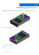
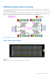
Table Of Contents
- Dell EMC DSS8440 Installation and Service Manual
- Contents
- About this document
- DSS8440 system overview
- Technical specifications
- Chassis dimensions
- Chassis weight
- Processor specifications
- PSU specifications
- Cooling fans specifications
- System battery specifications
- Expansion card riser specifications
- GPU specifications
- Memory specifications
- Drive specifications
- Ports and connectors specifications
- Environmental specifications
- System diagnostics and indicator codes
- Initial system setup and configuration
- Pre-operating system management applications
- Options to manage the pre-operating system applications
- System Setup
- Viewing System Setup
- System Setup details
- System BIOS
- Viewing System BIOS
- System BIOS Settings details
- System Information
- Viewing System Information
- System Information details
- Memory Settings
- Viewing Memory Settings
- Memory Settings details
- Processor Settings
- Viewing Processor Settings
- Processor Settings details
- SATA Settings
- Viewing SATA Settings
- SATA Settings details
- Boot Settings
- Viewing Boot Settings
- Choosing system boot mode
- Changing boot order
- Network Settings
- Viewing Network Settings
- Network Settings screen details
- UEFI iSCSI Settings
- Viewing UEFI iSCSI Settings
- UEFI iSCSI Settings details
- Integrated Devices
- Viewing Integrated Devices
- Integrated Devices details
- Serial Communication
- Viewing Serial Communication
- Serial Communication details
- System Profile Settings
- Viewing System Profile Settings
- System Profile Settings details
- System Security
- Viewing System Security
- System Security Settings details
- Creating a system and setup password
- Using your system password to secure the system
- Deleting or changing system and setup password
- Operating with setup password enabled
- Redundant OS Control
- Viewing Redundant OS Control
- Redundant OS Control screen details
- Miscellaneous Settings
- Viewing Miscellaneous Settings
- Miscellaneous Settings details
- iDRAC Settings utility
- Device Settings
- Dell Lifecycle Controller
- Boot Manager
- PXE boot
- Installing and removing system components
- Safety instructions
- Before working inside your system
- After working inside your system
- Recommended tools
- System cover
- Front bezel
- Air shroud
- Drives
- Drive backplane
- Power supply unit
- Expansion cards and expansion card risers
- Removing a GPU
- Installing a GPU
- Removing a GPU support bracket
- Installing a GPU support bracket
- Removing the PCIe switch board
- Installing the PCIe switch board
- Removing a GPU power interposer board
- Installing a GPU power interposer board
- Removing a butterfly module and riser 3 board
- Installing the riser 3 board and butterfly module
- Nvidia Tesla T4 GPU
- Nvidia A100 GPU and NVLink bridge
- Nvidia A40 GPU and NVLink bridge
- Processor and heat sink
- System memory
- Riser 2 module
- Riser 1 module
- Network daughter card
- System board tray module
- System board and power interposer board
- Backup battery
- Power distribution board
- PSB power interposer board
- Front control module
- Fan louvers
- Cooling fans
- Fan cage
- Handle
- Slide rail installation
- Cable Routing
- Dell EMC DSS8440 cable instruction
- 3M cable Installation-Config A left
- 3M cable Installation-Config A right
- Fan cable assembly to fan bracket
- Fan cable MB-PDB assembly to MB
- Fan cable MB-PDB assembly to PDB
- Front control cable assembly control board to MB
- GPU power cable assembly GPU card to PSB
- IDC cable MB-PDB assembly to PDB
- IDC cable MB-PDB assembly to MB
- IDC cable PDB-PIB assembly to PIB
- IDC cable PIB-PDB assembly to PDB
- IDC cable Riser1-PDB assembly to PDB
- IDC cable Riser1-PDB assembly to riser board1
- IDC cable PIB-PDB assembly to PDB
- IDC cable Riser 2- PDB assembly to riser board 2
- Mini SAS HD cable assembly PERC-HDBP
- Mini SAS HD cable assembly HDBP-MB
- Power cable BP-PDB assembly to BP
- Power cable BP-PDB assembly to PDB
- Power cable assembly to PDB
- Power cable assembly to PIB
- Power cable1 assembly to Riser1
- Power cable2 Riser-PDB assembly to PDB
- Power cable2 Riser-PDB assembly to Riser
- Jumpers and connectors
- Getting help

Notes, cautions, and warnings
NOTE: A NOTE indicates important information that helps you make better use of your product.
CAUTION: A CAUTION indicates either potential damage to hardware or loss of data and tells you how to avoid
the problem.
WARNING: A WARNING indicates a potential for property damage, personal injury, or death.
© 2019 -2021 Dell Inc. or its subsidiaries. All rights reserved. Dell, EMC, and other trademarks are trademarks of Dell Inc. or its subsidiaries.
Other trademarks may be trademarks of their respective owners.