Dell™ Dimension™ 3100/E310 Service Manual Before You Begin Removing the Computer Cover About Your Dell™ Dimension™ 3100/E310 Computer Advanced Troubleshooting Removing and Installing Parts Replacing the Computer Cover Specifications Technical Overview System Setup Notes, Notices, and Cautions NOTE: A NOTE indicates important information that helps you make better use of your computer. NOTICE: A NOTICE indicates either potential damage to hardware or loss of data and tells you how to avoid the problem.
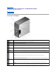
Back to Contents Page About Your Dell™ Dimension™ 3100/E310 Computer Dell™ Dimension™ 3100/E310 Service Manual Front View of Computer Back View of Computer Front View of Computer 1 cover latch release Use this latch to remove the cover. 2 CD or DVD activity light The drive light is on when the computer reads data from the CD or DVD drive. 3 CD or DVD eject button Press to eject a disk from the CD or DVD drive. 4 FlexBay drive Can contain an optional floppy drive or optional Media Card Reader.
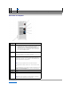
(4) Lights." 11 Service Tag Used to identify your computer when you access the Dell Support website or call technical support. Back View of Computer 1 power connector Insert the power cable. 2 sound card connectors (3) l l l 3 USB 2.0 connectors (4) Line-in connector — Use the blue line-in connector to attach a record/playback device such as a cassette player, CD player, or VCR. Line-out connector — Use the green line-out connector to attach headphones and most speakers with integrated amplifiers.
Back to Contents Page Advanced Troubleshooting Dell™ Dimension™ 3100/E310 Service Manual Dell Diagnostics System Lights Diagnostic Lights Beep Codes Dell Diagnostics CAUTION: Before you begin any of the procedures in this section, follow the safety instructions in the Product Information Guide. When to Use the Dell Diagnostics If you experience a problem with your computer, perform the checks in this section and run the Dell Diagnostics before you contact Dell for technical assistance.
Dell Diagnostics Main Menu 1. After the Dell Diagnostics loads and the Main Menu screen appears, click the button for the option you want. Option Function Express Test Performs a quick test of devices. This test typically takes 10 to 20 minutes and requires no interaction on your part. Run Express Test first to increase the possibility of tracing the problem quickly. Extended Test Performs a thorough check of devices.
Owner's Manual. Solid green power light and no beep An integrated system board device may be faulty. code but the computer locks up during POST Check the diagnostic lights to see if the specific problem is identified. If the problem is not identified, contact Dell for technical assistance. Diagnostic Lights CAUTION: Before you begin any of the procedures in this section, follow the safety instructions located in the Product Information Guide.
l floppy drive or hard drive); check system setup (see "System Setup") to make sure the boot sequence is correct for the devices installed on your computer. If the problem persists, contact Dell for technical assistance. During normal operation, all of the diagnostic lights turn on and then turn off before the system starts. If the system does not start, plug the computer into a working electrical outlet. Also see "Power Problems" in your Owner's Manual.
Back to Contents Page
Back to Contents Page Before You Begin Dell™ Dimension™ 3100/E310 Service Manual Getting Started Recommended Tools Turning Off Your Computer Before Working Inside Your Computer Getting Started This section provides procedures for removing and installing the components in your computer. Unless otherwise noted, each procedure assumes that the following conditions exist: l You have performed the steps in "Turning Off Your Computer" and "Before Working Inside Your Computer.
2. Disconnect any telephone or telecommunication lines from the computer. 3. Disconnect your computer and all attached devices from their electrical outlets, and then press the power button to ground the system board. CAUTION: To guard against electrical shock, always unplug your computer from the electrical outlet before opening the cover. 4. Open the computer cover.
Back to Contents Page Replacing the Computer Cover Dell™ Dimension™ 3100/E310 Service Manual CAUTION: Before you begin any of the procedures in this section, follow the safety instructions located in the Product Information Guide. 1. Ensure that all cables are connected and fold cables out of the way. Gently pull the power cables toward you so that they do not get caught underneath the drives. 2. Ensure that no tools or extra parts are left inside the computer. 3.
Back to Contents Page Removing the Computer Cover Dell™ Dimension™ 3100/E310 Service Manual CAUTION: Before you begin any of the procedures in this section, follow the safety instructions located in the Product Information Guide. CAUTION: To guard against electrical shock, always unplug your computer from the electrical outlet before removing the cover. 1. Follow the procedures in "Before You Begin.
Back to Contents Page Removing and Installing Parts Dell™ Dimension™ 3100/E310 Service Manual Memory Media Card Reader Cards CD/DVD Drive Drive Panels Processor Drives System Board Hard Drive Power Supply Floppy Drive Battery Memory DDR2 Memory Overview If your computer only has one memory module installed on the system board, you can increase your computer memory by installing an additional memory module. Your computer supports DDR2 memory.
1 memory connector closest to processor 2 securing clips (2) 3 connector 3. Align the notch on the bottom of the module with the crossbar in the connector. 1 cutouts (2) 2 memory module 3 notch 4 crossbar NOTICE: To avoid damage to the memory module, press the module straight down into the connector while applying equal force to each end of the module. 4. Insert the module into the connector until the module snaps into position.
Removing Memory CAUTION: Before you begin any of the procedures in this section, follow the safety instructions located in the Product Information Guide. NOTICE: To prevent static damage to components inside your computer, discharge static electricity from your body before you touch any of your computer's electronic components. You can do so by touching an unpainted metal surface on the computer chassis. 1. Follow the procedures in "Before You Begin." 2.
1 filler bracket 2 alignment guide 3 alignment bar 4 card retention door 5 release tab 2. Gently push the release tab on the inside of the card retention door to pivot the door open. Because the door is captive, it will remain in the open position. 3. If you are installing a new card, remove the filler bracket to create a card-slot opening. Then continue with step 5. 4. If you are replacing a card that is already installed in the computer, remove the card.
7. Before you close the card retention door, ensure that: l The tops of all cards and filler brackets are flush with the alignment bar. l The notch in the top of the card or filler bracket fits around the alignment guide. 1 card retention door 2 release tab 8. Close the card retention door by snapping it into place. NOTICE: Do not route card cables over or behind the cards. Cables routed over the cards can prevent the computer cover from closing properly or cause damage to the equipment. 9.
5. Replace the computer cover, reconnect the computer and devices to electrical outlets, and then turn them on. 6. Uninstall the driver for the card that you removed. 7. If you removed a sound card: 8. a. Enter system setup, select Audio Controller, and then change the setting to On. b. Connect external audio devices to the audio connectors on the back panel of the computer. If you removed an add-in network connector: a.
Removing the Optical Drive-Panel Insert 1 drive-panel insert 2 drive panel 3 drive panel-insert latch 1. Remove the drive panel. 2. Press the drive-panel insert latch inwards to unlatch it from the drive panel. 3. Pivot the drive-panel insert out and away from the drive panel. 4. Set the drive-panel insert aside in a secure location. Removing the FlexBay Drive-Panel Insert 1 drive-panel tab 2 drive-panel insert 1. Remove the drive panel. 2.
1 center drive-panel tab 2 drive-panel insert tab 3 drive panel 4 drive-panel insert latch 5 drive-panel insert 1. Slide the drive-panel insert tab under the center drive-panel tab. 2. Rotate the drive-panel insert into place and snap the drive-panel insert latch into place against the corresponding tab on the drive panel. Replacing the Drive Panel 1. Follow the procedures in "Before You Begin." 1 drive panel 2 sliding plate 3 sliding plate lever 2.
Your computer supports a combination of these devices: l Up to two serial ATA hard drives l One FlexBay drive (floppy drive or Media Card Reader) l Up to two CD or DVD drives 1 bay for second hard drive (optional) 2 hard drive 3 FlexBay for optional floppy drive or Media Card Reader 4 CD/DVD drive(s) Connect CD/DVD drives to the connector labeled "IDE" on the system board. Serial ATA hard drives should be connected to the connectors labeled "SATA0" or "SATA1" on the system board.
1 interface cable 2 interface connector Power Cable Connector To connect a drive using the power cable, locate the power input connector on the system board. 1 power input connector 2 power cable Connecting and Disconnecting Drive Cables When removing an IDE drive data cable, grasp the colored pull tab and pull until the connector detaches. When connecting and disconnecting a serial ATA data cable, hold the cable by the black connector at each end.
1 serial ATA data cable 2 power cable 3. Press the blue tabs on each side of the drive towards each other and slide the drive up and out of the computer. 1 tabs (2) 2 hard drive Installing a Hard Drive 1. Unpack the replacement hard drive, and prepare it for installation. 2. Check the documentation for the drive to verify that it is configured for your computer.
5. Check all connectors to ensure that they are properly cabled and firmly seated. 6. Replace the computer cover. NOTICE: To connect a network cable, first plug the cable into the network wall jack and then plug the cable into the computer. 7. Connect your computer and devices to electrical outlets, and turn them on. See the documentation that came with the drive for instructions on installing any software required for drive operation.
7. Connect the data cable to the drive and to the system board. 8. Check all connectors to ensure that they are properly cabled and firmly seated. 9. Replace the computer cover. NOTICE: To connect a network cable, first plug the cable into the network wall jack and then plug the cable into the computer. 10. Connect your computer and devices to electrical outlets, and turn them on. See the documentation that came with the drive for instructions on installing any software required for drive operation.
1 sliding plate lever 2 sliding plate 3 floppy drive 5. Check all cable connections, and fold cables out of the way to provide airflow for the fan and cooling vents. 6. Replace the drive panel. 7. Replace the computer cover. NOTICE: To connect a network cable, first plug the cable into the network device and then plug the cable into the computer. 8. Connect your computer and devices to their electrical outlets, and turn them on.
5. Attach the power and data cables to the floppy drive. 6. Connect the other end of the data cable to the connector labeled "FLOPPY" on the system board and route the cable through the clip on the shroud. 1 FlexBay 2 power cable 3 data cable 7. Check all cable connections, and fold cables out of the way to provide airflow for the fan and cooling vents. 8. Replace the drive panel. 9. Replace the computer cover.
1 cables 2 Media Card Reader (not present on all computers) 3. Disconnect the USB cable on the back of the Media Card Reader from the FlexBay USB connector on the system board and route the cable through the clip on the shroud. 1 sliding plate lever 2 sliding plate 3 Media Card Reader 4. Grasp the sliding plate lever and push it towards the base of the computer; then, hold it in place while you slide the Media Card Reader from the computer. 5.
Installing a Media Card Reader CAUTION: Before you begin any of the procedures in this section, follow the safety instructions located in the Product Information Guide. NOTICE: To prevent static damage to components inside your computer, discharge static electricity from your body before you touch any of your computer's electronic components. You can do so by touching an unpainted metal surface on the computer chassis. 1. Follow the procedures in "Before You Begin." 1 Media Card Reader 2 screws (3) 2.
10. Replace the drive panel. 11. Replace the computer cover. NOTICE: To connect a network cable, first plug the cable into the network device and then plug the cable into the computer. 12. Connect your computer and devices to their electrical outlets, and turn them on. CD/DVD Drive CAUTION: Before you begin any of the procedures in this section, follow the safety instructions located in the Product Information Guide.
1 sliding plate lever 2 sliding plate 3 CD/DVD drive 5. Check all cable connections, and fold cables out of the way to provide airflow for the fan and cooling vents. 6. Replace the drive panel. 7. Replace the computer cover. NOTICE: To connect a network cable, first plug the cable into the network device and then plug the cable into the computer. 8. Connect your computer and devices to their electrical outlets, and turn them on. Installing a CD/DVD Drive 1.
1 drive 2 screws (3) 4. Connect the power and data cables to the drive. 1 data cable 2 power cable 5. Check all cable connections, and fold cables out of the way to provide airflow for the fan and cooling vents. 6. Replace the computer cover. 7. Replace the drive panel. NOTICE: To connect a network cable, first plug the cable into the network device and then plug the cable into the computer. 8. Connect your computer and devices to their electrical outlets, and turn them on.
3. Rotate the heat sink and fan shroud assembly upward, and remove it from the computer. 1 heat sink and fan shroud assembly 2 captive screw housings (2) NOTICE: If you are installing a processor upgrade kit from Dell, discard the original heat sink. If you are not installing a processor upgrade kit from Dell, reuse the original heat sink when you install your new processor. 4. Open the processor cover by sliding the release lever out from beneath the center cover latch on the socket.
1. Unpack the new processor, being careful not to touch the underside of the processor. NOTICE: You must position the processor correctly in the socket to avoid permanent damage to the processor and the computer when you turn on the computer. 2. If the release lever on the socket is not fully extended, move it to that position. 3. Orient the front and rear alignment notches on the processor with the front and rear alignment notches on the socket. 4.
1 heat sink and fan shroud assembly 2 heat sink assembly bracket 3 captive screw housings (2) 9. Replace the computer cover. NOTICE: To connect a network cable, first plug the cable into the network wall jack and then plug the cable into the computer. 10. Connect your computer and devices to electrical outlets, and turn them on. System Board CAUTION: Before you begin any of the procedures in this section, follow the safety instructions located in the Product Information Guide.
1 system board 2 screws (10) 6. Slide the system board assembly toward the front of the computer, and then lift the board up and away. 7. Place the system board assembly that you just removed next to the replacement system board to ensure it is identical. Replacing the System Board 1. Gently align the board and slide it toward the back of the computer. 2. Replace the screws attaching the system board. 3. Replace any components and cables that you removed from the system board. 4.
1 release button 2 power supply 3 screws (4) 4 AC power connector 5. Slide the power supply approximately 1 inch towards the front of the computer. 6. Lift the power supply up and out of the computer. Replacing the Power Supply CAUTION: Before you begin any of the procedures in this section, follow the safety instructions located in the Product Information Guide. 1. Slide the power supply into place. 2. Replace the screws that secure the power supply to the back of the computer frame. 3.
NOTICE: To prevent static damage to components inside your computer, discharge static electricity from your body before you touch any of your computer's electronic components. You can do so by touching an unpainted metal surface on the computer chassis. A coin-cell battery maintains computer configuration, date, and time information. The battery can last several years. If you have to repeatedly reset time and date information after turning on the computer, replace the battery.
Back to Contents Page Specifications Dell™ Dimension™ 3100/E310 Service Manual Processor Processor type Intel® Pentium® 4 with Hyper-Threading technology NOTE: Not all Pentium 4 processors support HyperThreading technology.
connector one x1 connector size 36 pins connector data width (maximum) 1 PCI Express lane Drives Externally accessible: one 3.5-inch drive bay (FlexBay) two 5.
Voltage (see the safety instructions located in the Product Information Guide for important voltage setting information) Backup battery 90 to 135 V and 180 to 265 V at 50/60 Hz 3-V CR2032 lithium coin cell Physical Height 41.4 cm (16.3 inches) Width 18.8 cm (7.4 inches) Depth 45.7 cm (18.0 inches) Weight 12.
Back to Contents Page System Setup Dell™ Dimension™ 3100/E310 Service Manual Clearing Forgotten Passwords Clearing CMOS Settings Overview Use system setup as follows: l To change the system configuration information after you add, change, or remove any hardware in your computer l To set or change a user-selectable option such as the user password l To read the current amount of memory or set the type of hard drive installed Before you use system setup, it is recommended that you write down the syste
NOTE: Depending on your computer and installed devices, the items listed in this section may not appear, or may not appear exactly as listed. System Lists system information such as the computer name, the BIOS version number and date, system tags, and other system-specific information. System Info NOTE: The system name listed in the BIOS may not appear exactly as the name that appears on the computer or in the computer's documentation.
System Password Displays the current status of the system's password security feature and allows a new system password to be assigned and verified. Password Status This option locks the system password field with the setup password. When the field is locked, you can no longer disable password security by pressing when the computer starts. Execute Disable This field specifies whether Execute Disable Memory Protection Technology will be on or off.
1. If you are booting to a USB device, connect the USB device to a USB connector. 2. Turn on (or restart) your computer. 3. When F2 = Setup, F12 = Boot Menu appears in the upper-right corner of the screen, press . If you wait too long and the operating system logo appears, continue to wait until you see the Microsoft Windows desktop. Then shut down your computer and try again. The Boot Device Menu appears, listing all available boot devices. Each device has a number next to it. 4.
9. 10. Locate the 3-pin password jumper (PSWD) on the system board and attach the jumper to pins 1 and 2 to reenable the password feature. Replace the computer cover. NOTICE: To connect a network cable, first plug the cable into the network device and then plug the cable into the computer. 11. Connect your computer and devices to electrical outlets, and turn them on.
Back to Contents Page Technical Overview Dell™ Dimension™ 3100/E310 Service Manual Inside View of Your Computer System Board Components Power Supply DC Connector Pin Assignments Inside View of Your Computer 1 bay for optional second hard drive 2 hard drive 3 floppy drive* 4 CD or DVD drive 5 power supply 6 system board System Board Components
clear CMOS jumper 1 9 (RTCRST) main power connector 2 fan connector (CPU FAN) 10 IDE drive connector 3 floppy drive connector (FLOPPY) 11 4 processor and heat sink connector 12 PCI Express x1 card connector 5 processor power connector 13 PCI card connectors 6 memory module connectors (1, 2) 14 FlexBay USB connector password jumper (PSWD) SATA connectors 7 15 battery socket (BATTERY) (SATA-0 and SATA-1) 8 front panel I/O connector Jumper Settings The jumper locations are shown below.
Power Supply DC Connector Pin Assignments DC Power Connector P1 Pin Number Signal Name Color Wire Gauge 1 +3.3 VDC Orange 18-AWG 2 +3.3 VDC Orange 18-AWG 3 COM Black 18-AWG 4 +5 VDC Red 18-AWG 5 COM Black 18-AWG 6 +5 VDC Red 18-AWG 7 COM Black 18-AWG 8 POK Gray 18-AWG 9 +5 VFP Purple 18-AWG 10 +12 VB DC Yellow 18-AWG 11 +12VB DC Yellow 18-AWG 12 +3.3 VDC Orange 18-AWG 13 +3.
23 +5 VDC Red 18-AWG 24 COM Black 18-AWG DC Power Connector P2 Pin Number Signal Name 18-AWG Wire 1 COM Black 2 COM Black 3 +12 VA DC Yellow 4 +12 VA DC Yellow DC Power Connect P3 and P5 Pin Number Signal Name 18-AWG Wire 1 +3.
1 +12 VA DC Yellow 2 COM Black 3 COM Black 4 +5 VDC Red Back to Contents Page