Dell Latitude E5440 Owner's Manual Regulatory Model: P44G Regulatory Type: P44G001
Notes, Cautions, and Warnings NOTE: A NOTE indicates important information that helps you make better use of your computer. CAUTION: A CAUTION indicates either potential damage to hardware or loss of data and tells you how to avoid the problem. WARNING: A WARNING indicates a potential for property damage, personal injury, or death. Copyright © 2014 Dell Inc. All rights reserved. This product is protected by U.S. and international copyright and intellectual property laws.
Contents 1 Working on Your Computer................................................................................... 5 Before Working Inside Your Computer................................................................................................ 5 Turning Off Your Computer..................................................................................................................7 After Working Inside Your Computer..................................................................................
Removing the Display Hinge.............................................................................................................. 25 Installing the Display Hinge................................................................................................................ 26 Removing the Palmrest....................................................................................................................... 27 Installing the Palmrest.............................................................
Working on Your Computer 1 Before Working Inside Your Computer Use the following safety guidelines to help protect your computer from potential damage and to help to ensure your personal safety. Unless otherwise noted, each procedure included in this document assumes that the following conditions exist: • You have read the safety information that shipped with your computer. • A component can be replaced or--if purchased separately--installed by performing the removal procedure in reverse order.
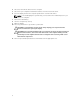
4. Disconnect all network cables from the computer. 5. Disconnect your computer and all attached devices from their electrical outlets. 6. Close the display and turn the computer upside-down on a flat work surface. NOTE: To avoid damaging the system board, you must remove the main battery before you service the computer. 7. Remove the main battery. 8. Turn the computer top-side up. 9. Open the display. 10. Press the power button to ground the system board.
Turning Off Your Computer CAUTION: To avoid losing data, save and close all open files and exit all open programs before you turn off your computer. 1. Shut down the operating system: • In Windows 8: – Using a touch-enabled device: a. Swipe in from the right edge of the screen, opening the Charms menu and select Settings. b. Select the and then select Shut down – Using a mouse: • a. Point to upper-right corner of the screen and click Settings. b. Click the and select Shut down.
5. 8 Turn on your computer.
Removing and Installing Components 2 This section provides detailed information on how to remove or install the components from your computer.
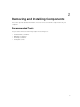
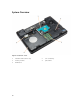
System Overview Figure 1. Inside View — Back 1. 3. 5. 10 hard drive with isolation cap memory module WLAN card 2. 4.
Figure 2. Inside view — Front 1. 3. 5. 7. power connector system fan speakers system board 2. 4. 6. 8.
Removing the Battery 1. Follow the procedures in Before Working Inside Your Computer. 2. Perform the following steps: a. Slide the battery release latches into the unlock position. b. Push and remove the battery from the computer. Installing the Battery 1. Slide the battery into its slot until it clicks into place. 2. Follow the procedures in After Working Inside Your Computer. Removing the SD Card 1. Follow the procedures in Before Working Inside Your Computer. 2.
Removing the ExpressCard 1. Follow the procedures in Before Working On Your Computer. 2. Perform the following steps: a. Push in on the ExpressCard to release from the computer [1]. b. Slide the ExpressCard out of the computer [2]. Installing the ExpressCard 1. Slide the ExpressCard in its slot until it clicks in place. 2. Follow the procedures in After Working Inside Your Computer. Removing the SIM Card 1. Follow the procedures in Before Working On Your Computer. 2. Remove the battery. 3.
Removing the Display Bezel 1. Follow the procedures in Before Working Inside Your Computer. 2. Remove the battery. 3. Perform the following steps: a. Pry up the bottom edge of the display bezel. b. Work your way around the sides and top edge of the display bezel. 4. Remove the display bezel from the computer. Installing the Display Bezel 1. Place the display bezel onto the display assembly. 2.
3. Remove the screws that secure the display panel and flip the panel over. 4. Perform the following steps: a. Lift the mylar tape and disconnect the low-voltage differential signaling (LVDS) cable from the back of the display panel. b. Remove the display panel from the display assembly. Installing the Display Panel 1. Place the display panel to the display assembly. 2. Align the display panel in its original position. 3.
Removing the Camera 1. Follow the procedures in Before Working Inside Your Computer. 2. Remove: a. battery b. display bezel 3. Perform the following steps: a. Remove the screw that secures the camera and microphone module. b. Disconnect the camera cable. c. Lift and remove the camera and microphone module. Installing the Camera 1. Place the camera and microphone module on its place. 2. Connect the camera cable. 3. Tighten the screw to secure the camera and microphone module. 4. Install: a.
3. Perform the following steps: a. Pry up the keyboard trim on its sides and the top edge. b. Lift upwards and remove the keyboard trim from the computer. Installing the Keyboard Trim 1. Align the keyboard trim to its place. 2. Press along the sides of the keyboard trim until it snaps in place. 3. Install the battery. 4. Follow the procedures in After Working Inside Your Computer.
Removing the Keyboard 1. Follow the procedures in Before Working Inside Your Computer. 2. Remove: a. battery b. keyboard trim 3. Remove the screws at the back of the computer and flip the computer over. 4. Remove the screws that secure the keyboard [1] and lift the keyboard from the computer [2] and [3].
5. Disconnect the keyboard cable and remove the keyboard from the computer. Installing the Keyboard 1. Connect the keyboard cable to the keyboard. 2. Place the keyboard into its place until all the metal tabs fit into their positions. 3. Press down on the keyboard to the left and right side ensuring that all the snaps are fully engaged with the computer. 4. Install the screws to secure the keyboard to the palmrest. 5. Install the screws at the back of the computer. 6. Install: a.
3. Perform the following steps: a. Remove the screws that secure the base cover. b. Slide the base cover towards the front of the system and remove it from the computer. Installing the Base Cover 1. Slide the base cover into its slot until it clicks into place. 2. Install the screws that secure the base cover to the computer. 3. Install the battery. 4. Follow the procedures in After Working Inside Your Computer. Removing the Optical Drive 1.
3. Perform the following steps: a. Remove the screw that secures the optical drive to the computer. b. Push the optical drive away to remove it from the computer. 4. After removing the optical-drive bracket, perform the following steps: a. Remove the screws that secure the optical-drive bracket [1]. b. Remove the optical-drive bracket from the optical drive [2]. 5. Disengage the optical drive bezel tabs to separate the optical drive bezel from the optical drive. 6. Remove the optical-drive bezel.
Removing the Hard Drive 1. Follow the procedures in Before Working Inside Your Computer. 2. Remove: a. battery b. base cover 3. Perform the following steps: a. Remove the screws that secure the hard-drive bracket in place. b. Slide and pull the hard drive to remove from its connectors. 4. 22 Remove the hard-drive isolation cap from the hard drive.
Installing the Hard Drive 1. Engage the hard-drive isolation cap to the hard drive. 2. Place the hard drive on its connector. 3. Place the hard-drive bracket on the hard drive and tighten the screws to secure the hard-drive bracket in place. 4. Install: a. base cover b. battery 5. Follow the procedures in After Working Inside Your Computer. Removing the Memory Module 1. Follow the procedures in Before Working Inside Your Computer. 2. Remove: a. battery b. base cover 3.
Installing the Memory Module 1. Insert the memory into the memory socket. 2. Press the clips to secure the memory module to the system board. 3. Install: a. base cover b. battery 4. Follow the procedures in After Working Inside Your Computer. Removing the WLAN Card 1. Follow the procedures in Before Working Inside Your Computer. 2. Remove: a. battery b. base cover 3. Perform the following steps: a. Disconnect the antennae cables from the WLAN card. b.
3. Perform the following steps: a. Disconnect the coin-cell battery cable from the system board. b. Pry and remove the coin-cell battery from the adhesive. Installing the Coin-Cell Battery 1. Place the coin-cell battery on the system board with adhesive side downwards. 2. Connect the coin-cell battery cable to the system board. 3. Install: a. base cover b. battery 4. Follow the procedures in After Working Inside Your Computer. Removing the Display Hinge 1.
3. Remove the screws that secure the display hinge at the back of the computer. 4. Remove the screws that secure the display hinge at the front of the computer. Press and remove the display hinge from the computer. Installing the Display Hinge 1. Place the display hinge on the computer. 2. Tighten the screws to secure the display hinge at the front and back of the computer. 3. Install: a. b. c. d. 4.
Removing the Palmrest 1. Follow the procedures in Before Working Inside Your Computer. 2. Remove: a. b. c. d. e. f. g. h. i. 3. SD card battery base cover keyboard trim keyboard memory optical drive hard drive display hinge Remove the screws at the bottom of the computer.
4. Disconnect: a. b. c. d. 5. media-buttons cable touch-pad cable fingerprint-scanner cable power-button cable Perform the following steps: a. Remove the screws that secure the palmrest of the computer. b.
Installing the Palmrest 1. Align the palmrest assembly to its original position in the computer and snap it into place. 2. Connect the following cables to the system board: a. b. c. d. power-button cable fingerprint-scanner cable touch-pad cable media button cable 3. Tighten the screws to secure the palmrest at the front and back of the computer. 4. Install: a. b. c. d. e. f. g. h. i. 5.
3. Disconnect and remove WLAN cable from its routing channels. 4. Perform the following steps: a. Remove the screws that secure the display-cable connector and remove it from the system board. b. Disconnect the display cables from the system board.
5. Remove the screws that secure the display assembly in place and lift to remove the display assembly from the computer. NOTE: The above display assembly removal procedures are applicable for both Touch and Nontouch versions of the computer. Installing the Display Assembly 1. Tighten the screws that secure the display assembly in place. 2. Insert the WLAN cable through the holes on the chassis. 3.
Removing the ExpressCard Cage 1. Follow the procedures in Before Working Inside Your Computer. 2. Remove: a. b. c. d. e. f. g. 3. SD card battery base cover keyboard trim keyboard display hinge palmrest Perform the following steps: a. Remove the screws that secure the ExpressCard cage. b. Lift and remove the ExpressCard cage from the computer. Installing the ExpressCard Cage 1. Align the ExpressCard cage to its original position on the computer and snap it into place. 2.
Removing the System Fan 1. Follow the procedures in Before Working Inside Your Computer. 2. Remove: a. b. c. d. e. f. g. h. i. j. 3. SD card battery base cover keyboard trim keyboard memory optical drive hard drive display hinge palmrest Disconnect: a. system-fan cable b.
4. Remove the screws that secure the system fan and lift the system fan to remove from the computer. Installing the System Fan 1. Place the system fan on the computer. 2. Connect the system-fan cable to the system board. 3. Connect the I/O board cable to its connector. 4. Tighten the screws to secure the system fan on the computer. 5. Install: a. b. c. d. e. f. g. h. i. j. 6.
Removing the System Board 1. Follow the procedures in Before Working Inside Your Computer. 2. Remove: a. b. c. d. e. f. g. h. i. j. k. l. m. 3. SD card battery base cover keyboard trim keyboard memory optical drive hard drive WLAN card display hinge palmrest system fan ExpressCard cage Disconnect: a. coin-cell battery cable b.
4. Flip the computer and disconnect: a. power cable b. status-light board cable c. I/O board cable 5. Perform the following steps: a. Remove the screws that secure the display-cable connector and remove it from the system board. b. Disconnect the display cables and power-connector cable from the system board.
6. Remove the screws that secure the system board and lift the system board to remove from the computer. Installing the System Board 1. Align the system board into its original position on the computer. 2. Replace and tighten the screws to secure the system board to the computer. 3. Connect the following cables: a. I/O board cable b. power-connector cable c. status-light board cable 4. Turn over the computer and connect the coin-cell battery cable and speaker cable to the system board. 5.
Removing the Heatsink 1. Follow the procedures in Before Working Inside Your Computer. 2. Remove: a. b. c. d. e. f. g. h. i. j. k. l. m. n. 3. SD card battery base cover keyboard trim keyboard memory optical drive hard drive WLAN card display hinge palmrest system fan ExpressCard cage system board Perform the following steps: a. Remove the screws that secure the heatsink in place. b. Lift to remove the heatsink from the computer. Installing the Heatsink 1. Place the heatsink on the system board. 2.
3. Install: a. b. c. d. e. f. g. h. i. j. k. l. m. n. 4. system board ExpressCard cage system fan palmrest display hinge WLAN card hard drive optical drive memory keyboard keyboard trim base cover battery SD card Follow the procedures in After Working Inside Your Computer. Removing the I/O Board (Left) 1. Follow the procedures in Before Working Inside Your Computer. 2. Remove: a. b. c. d. e. f. g. h. i. j. k. l. m. n.
3. Perform the following steps: a. Remove the screw that secures the left I/O board on the computer. b. Lift the I/O board and remove from the computer. Installing the I/O Board (Left) 1. Place the I/O board on the computer. 2. Tighten the screw to secure the I/O board to the computer. 3. Install: a. b. c. d. e. f. g. h. i. j. k. l. m. n. 4.
Removing the I/O Board (Right) 1. Follow the procedures in Before Working Inside Your Computer. 2. Remove: a. b. c. d. e. f. g. h. i. j. k. l. m. n. 3. SD card battery base cover keyboard trim keyboard memory optical drive hard drive WLAN card display hinge palmrest system fan ExpressCard cage system board Perform the following steps: a. Remove the screws that secure the I/O board on the computer. b. Lift the I/O board and remove from the computer. Installing the I/O Board (Right) 1.
3. Install: a. b. c. d. e. f. g. h. i. j. k. l. m. n. 4. system board ExpressCard cage system fan palmrest display hinge WLAN card hard drive optical drive memory keyboard keyboard trim base cover battery SD card Follow the procedures in After Working Inside Your Computer. Removing the Power Connector 1. Follow the procedures in Before Working Inside Your Computer. 2. Remove: a. b. c. d. e. f. g. h. i. j. k. l. m. n.
3. Perform the following steps: a. Remove the power-connector cable from the routing channels. b. Lift and remove the power connector from the computer. Installing the Power Connector 1. Place the power connector on its place in the computer. 2. Route the power-connector cable on its routing channels. 3. Install: a. b. c. d. e. f. g. h. i. j. k. l. m. n. 4.
Removing the Speakers 1. Follow the procedures in Before Working Inside Your Computer. 2. Remove: a. b. c. d. e. f. g. h. i. j. k. l. m. n. 3. SD memory card battery base cover keyboard trim keyboard memory optical drive hard drive WLAN card display hinge palmrest system fan ExpressCard cage system board Perform the following steps: a. Remove the speaker cable from the routing channels. b. Remove the screws that secure the speakers from the computer. c. Lift and remove the speakers from the computer.
4. Install: a. b. c. d. e. f. g. h. i. j. k. l. m. n. 5. system board ExpressCard cage system fan palmrest display hinge WLAN card hard drive optical drive memory keyboard keyboard trim base cover battery SD card Follow the procedures in After Working Inside Your Computer. Removing the Status-Light Board 1. Follow the procedures in Before Working Inside Your Computer. 2. Remove: a. b. c. d. e. f. g. h. i. j. k. l. m. n. o.
3. Perform the following steps: a. Remove the LED cover. b. Disconnect the status-light board cable and remove the screw that secures the status-light board. c. Lift and remove the status-light board from the computer. Installing the Status-Light Board 1. Place the status-light board on its place on the computer. 2. Connect the status-light board cable to its connector. 3. Tighten the screw to secure the status-light board on the computer. 4. Place the LED cover on the status-light board. 5.
System Setup 3 System Setup enables you to manage your computer hardware and specify BIOS‐level options.
Table 1. Navigation Keys Keys Navigation Up arrow Moves to the previous field. Down arrow Moves to the next field. Allows you to select a value in the selected field (if applicable) or follow the link in the field. Spacebar Expands or collapses a drop‐down list, if applicable. Moves to the next focus area. NOTE: For the standard graphics browser only. Moves to the previous page till you view the main screen.
Option Description By default, all the options are checked. You can also deselect any option or change the boot order. Boot List Option Allows you to change the boot list option. • • Legacy UEFI Advanced Boot Options This option allows you the legacy option ROMs to load. By default, the Enable Legacy Option ROMs is unchecked. Date/Time Allows you to change the date and time. Table 3. System Configuration Option Description Integrated NIC Allows you to configure the integrated network controller.
Option Description • SMART Reporting This field controls whether hard drive errors for integrated drives are reported during system startup. This technology is part of the SMART (Self Monitoring Analysis and Reporting Technology) specification. This option is disabled by default. • USB Configuration SATA-3 Enable SMART Reporting This field configures the integrated USB controller. If Boot Support is enabled, the system is allowed to boot any type of USB Mass Storage Devices (HDD, memory key, floppy).
Option Description You can also enable or disable Media Card. Table 4. Video Option Description LCD Brightness Allows you to set the display brightness depending up on the power source (On Battery and On AC). NOTE: The Video setting will only be visible when a video card is installed into the system. Table 5. Security Option Description Admin Password Allows you to set, change, or delete the administrator (admin) password.
Option Description Default Setting: Disabled Password Change Allows you to enable the disable permission to the System and Hard Drive passwords when the admin password is set. Default Setting: Allow Non-Admin Password Changes is selected Non-Admin Setup Changes Allows you to determine whether changes to the setup options are allowed when an Administrator Password is set. If disabled the setup options are locked by the admin password.
Option Description • Expert Key Management Enable Allows you to manipulate the security key databases only if the system is in Custom Mode. The Enable Custom Mode option is disabled by default. The options are: • • • • PK KEK db dbx If you enable the Custom Mode, the relevant options for PK, KEK, db, and dbx appear.
Option Description Hyper-Thread Control Allows you to enable or disable the HyperThreading in the processor. Default Setting: Enabled Rapid Start Technology This option might improve the battery life by automatically putting the computer in to a low power state during Sleep, after a user-specified amount of time. Default Setting: Disabled Table 8.
Option Description Block Sleep This option lets you block entering to sleep (S3 state) in Operating System environment. Block Sleep (S3 state) - This option is disabled by default. Peak Shift This option enables you to minimize the AC power consumption during the peak power times of day. After you enable this option, your system runs only in battery even if the AC is attached. Advanced Battery Charge Configuration This option enables you to maximize the battery health.
Option Description • • Fn Key Only: This option is enabled by default. By Numlock NOTE: The Keyboard (Embedded) option is not supported in Latitude E5540 Mouse/Touchpad Allows you to define how the system handles mouse and touch pad input. The options are: • • • Numlock Enable Serial Mouse PS2 Mouse Toushpad/PS-2 Mouse: This option is enabled by default. Allows you to enable the Numlock option when the computer boots.
Option Description Trusted Execution This option specifies whether a Measured Virtual Machine Monitor (MVMM) can utilize the additional hardware capabilities provided by Intel Trusted Execution Technology. The TPM virtualization Technology, and Virtualization technology for direct I/O must be enabled to use this feature. Trusted Execution — disabled by default. Table 11. Wireless Option Description Wireless Switch Allows to set the wireless devices that can be controlled by the wireless switch.
Table 13. System Logs Option Description BIOS Events Allows you to view and clear the System Setup (BIOS) POST events. Thermal Events Allows you to view and clear the System Setup (Thermal) events. Power Events Allows you to view and clear the System Setup (Power) events. Updating the BIOS It is recommended to update your BIOS (system setup), on replacing the system board or if an update is available. For laptops, ensure that your computer battery is fully charged and connected to a power outlet 1.
CAUTION: The password features provide a basic level of security for the data on your computer. CAUTION: Anyone can access the data stored on your computer if it is not locked and left unattended. NOTE: Your computer is shipped with the system and setup password feature disabled. Assigning a System Password and Setup Password You can assign a new System Password and/or Setup Password or change an existing System Password and/or Setup Password only when Password Status is Unlocked.
4. Select Setup Password, alter or delete the existing setup password and press or . NOTE: If you change the System and/or Setup password, re-enter the new password when promoted. If you delete the System and/or Setup password, confirm the deletion when promoted. 5. Press and a message prompts you to save the changes. 6. Press to save the changes and exit from the System Setup. The computer reboots.
Diagnostics 4 If you experience a problem with your computer, run the ePSA diagnostics before contacting Dell for technical assistance. The purpose of running diagnostics is to test your computer's hardware without requiring additional equipment or risking data loss. If you are unable to fix the problem yourself, service and support personnel can use the diagnostics results to help you solve the problem.
Device Status Lights Icon Description Turns on when you turn on the computer and blinks when the computer is in a power management mode. Turns on when the computer reads or writes data. Turns on steadily or blinks to indicate battery charge status. Turns on when wireless networking is enabled.
5 Specifications NOTE: Offerings may vary by region. For more information regarding the configuration of your computer, click Start (Start icon) → Help and Support, and then select the option to view information about your computer. Table 14. System Information Feature Specification DRAM bus width 64-bit Flash EPROM SPI 32Mbits + 64Mbits PCIe Gen1 bus 100 MHz External Bus Frequency DMI (5GT/s) Table 15.
Feature Specification • without Express Card I/O on Discrete Graphic and all UMA Graphic Configurations • Supports mSATA and WWAN on Latitude E5440 Supports mSATA on Latitude E5540. Table 18.
Feature Specification USB 2.0 • • one 4–pin USB 2.0–compliant connector (E5440) two 4-pin USB 2.0-compliant connectors (E5540) NOTE: The USB 2.0 connector at the back of the Latitude E5540 computer, gets deactivated, when the Latitude E5540 computer is connected to the docking station. USB 3.0 two USB 3.0–compliant connectors Memory card reader one 8-in-1 memory card reader Docking port one Subscriber Identity Module (SIM) port one (E5440 only) Table 22.
Feature Specification Active area (X/Y) 344.23 mm x 193.54 mm Maximum resolution • • Maximum Brightness 220 nits for HD, 300 nits for FHD 1366 x 768 pixels 1920 x 1080 pixels Operating angle 0° (closed) to 135° Refresh rate 60 Hz Minimum Viewing angles: Horizontal • • +/- 40° for HD +/- 60° for FHD Vertical • • +10°/-30° for HD +/-50° for FHD Pixel pitch: Latitude E5440 0.2265 mm x 0.2265 mm Latitude E5540 • • 0.2520 mm x 0.2520 mm for HD 0.1790 x 0.1790 for FHD Table 23.
Feature Specification 4- and 6-cell 208.00 mm (8.18 inches) 9-cell 214.00 mm (8.43 inches) Depth 4- and 6-cell 48.08 mm (1.89 inches) 9-cell 71.79 mm (2.83 inches) Weight 4-cell 240.00 g (0.53 lb) 6-cell 344.73 g (0.76 lb) 9-cell 508.20 g (1.12 lb) Voltage 4-cell 14.8 VDC 6- and 9-cell 11.
Feature Non-Operating Latitude E5440 Latitude E5540 –40 °C to 70 °C (–40 °F to 158 °F) –40 °C to 70 °C (–40 °F to 158 °F) Table 27. Physical Physical Latitude E5440 Touch Height Latitude E5540 Non-touch Touch Non-touch Front - 27.70 mm (1.09 inches) Front - 25.20 mm (0.99 inch) Front - 28.25 mm (1.11 inches) Front - 26.00 mm (1.02 inches) Back - 32.20 mm (1.27 inches) Back - 28.65 mm (1.13 inches) Back - 33.60 mm (1.32 inches) Back - 29.70 mm (1.17 inches) Width 338.00 mm (13.
Contacting Dell 6 NOTE: If you do not have an active Internet connection, you can find contact information on your purchase invoice, packing slip, bill, or Dell product catalog. Dell provides several online and telephone-based support and service options. Availability varies by country and product, and some services may not be available in your area. To contact Dell for sales, technical support, or customer service issues: 1. Visit dell.com/support 2. Select your support category. 3.