
White Papers


6
Each bit of the read byte indicates the current level of a pin.
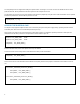
The following code gives a more complete example. It is a function to change the level of the pin specified by the given parameter “pin”,
instead of changing all the pins. The value of the parameter “pin” ranges from 0 to 7 to indicate the pin in GPO0 to GPO7.
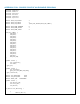
void set_pin_level(int pin, int level)
{
enter_extended_function_mode();
// Select virtual device 8
lpc_reg_write(0x07, 8);
// Read pin data
int bit_map = lpc_reg_read(0xE1);
if ( level ) // change pin to high
bit_map |= (1 << pin);
else // change pin to low
bit_map &= ~(1 << pin);
// Write pin data
lpc_reg_write(0xE1, bit_map);
leave_extended_function_mode();
}
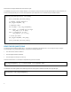
READ THE GPI (INPUT) PINS
The eight input pins GPIO 8 IN (GPI0, GPI1,… and GPI7) are controlled on the virtual device 7 on the Super IO chip. The way to
access GPI pins is very similar with GPO pins, except for the following differences:
The virtual device number is different.
The data register address is different.
The data register for GPI pins is read-only.
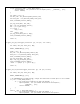
Select the virtual device 7 on the Super IO chip before any pins are accessed:
lpc_reg_write(0x07, 7); // write value 7 to register 0x07
The address of the data register is F5h. Read a byte from the data register to retrieve the levels of the eight GPI pins:
int bit_map = lpc_reg_read(0xF5);