Dell EMC ML3 Tape Library User's Guide
Information in this document is subject to change without notice. Copyright © 2020 Dell Inc. or its subsidiaries. All rights reserved. Dell, EMC, and other trademarks are trademarks of Dell Inc. or its subsidiaries. Other trademarks may be trademarks of their respective owners. Printed September 2020.
Read this FIRST Regulatory information • The library must be installed in a restricted area. • Only personnel with technical and product safety training should have access to the library. • The library must be properly installed in an office or industrial environment with shielded cables and adequate grounding of SAS interface and input power to comply with regulations and standards.
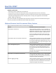
Table 1. Minimum firmware levels for common library features (continued) Feature Minimum Firmware Levels Required LTO M8 media Library Firmware must be at 1.1.1.1-B00 or greater to support the M8 media feature. Drive firmware must be at HB82 or greater to support the M8 media feature. Ensure that any device drivers are at the minimum level that is required to support the 3U library. Sequential Mode Library Firmware must be at 1.1.1.2-A00 or greater to support Sequential Mode.
Contents ............................................................................................................................. ii Read this FIRST....................................................................................................iii Minimum firmware levels for common library features............................................................................. iii Contacting Dell..........................................................................................................
Identifying Library Module components................................................................................................... 40 Preparing top and bottom modules.......................................................................................................... 40 Installing modules in a rack...................................................................................................................... 43 Installing a tabletop module....................................................
Appendix B. Management GUI functions and roles ............................................. 151 Appendix C. LTO media...................................................................................... 157 Data cartridges........................................................................................................................................ 157 Cartridge Read/Write compatibility...................................................................................................
Index................................................................................................................
Figures 1. Two module tape library............................................................................................................................... 1 2. Base Module ................................................................................................................................................. 2 3. Expansion Module......................................................................................................................................... 3 4. Base Module............
23. Psychrometric chart showing recommended and allowable operating environments for the tape library..........................................................................................................................................................25 24. Types of receptacles................................................................................................................................. 31 25. Removing the module from the box.............................................................
48. Full-height FC dual port............................................................................................................................ 51 49. Half-height FC single port......................................................................................................................... 51 50. Half-height SAS dual port......................................................................................................................... 52 51. IP address selection.......................
73. Unlocking the spooling cable and placing it in its cradle.......................................................................134 74. Spooling cable in park position.............................................................................................................. 134 75. Pins are aligned horizontally.................................................................................................................. 135 76. Installing the spooling cable.........................................
Tables 1. Minimum firmware levels for common library features...............................................................................iii 2. Module designations..................................................................................................................................... 1 3. Minimum and maximum storage configurations.......................................................................................... 2 4. Library configurations...............................................
24. Half-height SAS dual port......................................................................................................................... 52 25. Main screen elements...............................................................................................................................60 26. Navigation Dock........................................................................................................................................ 61 27. Status icons.............................
49. Cartridges and VOLSERs compatible with the LTO Tape Drives........................................................... 161 50. Location of the write-protect switch...................................................................................................... 163 51. Environment for storage and shipping the LTO tape cartridges............................................................166 52. General REST API information...............................................................................
74. Responses...............................................................................................................................................178 75. Security................................................................................................................................................... 178 76. Responses...............................................................................................................................................179 77. Security................
99. Security................................................................................................................................................... 185 100. Parameters............................................................................................................................................185 101. ManufacturingMode..............................................................................................................................185 102. Responses.......................
124. Responses.............................................................................................................................................191 125. Security................................................................................................................................................. 191 126. Parameters............................................................................................................................................191 127. DriveNumber...............
149. LibraryInfo............................................................................................................................................ 203 150. LibraryStatus.........................................................................................................................................203 151. LicenseInfo........................................................................................................................................... 203 152. MediaInfoData..............
Safety and environmental notices When this product is used, observe the danger, caution, and attention notices that are contained in this guide. The notices are accompanied by symbols that represent the severity of the safety condition. The sections that follow define each type of safety notice and give examples. Danger and Caution notices Danger notices A danger notice calls attention to a situation that is potentially lethal or extremely hazardous to people.
To prevent a possible shock from touching two surfaces with different protective ground(earth), use one hand, when possible, to connect or disconnect signal cables. (D001) Overloading a branch circuit is potentially a fire hazard and a shock hazard under certain conditions. To avoid these hazards, ensure that your system electrical requirements do not exceed branch circuit protection requirements.
• When possible, use one hand only to connect or disconnect signal cables. • Never turn on any equipment when there is evidence of fire, water, or structural damage. • Do not attempt to switch on power to the machine until all possible unsafe conditions are corrected. • Assume that an electrical safety hazard is present. Perform all continuity, grounding, and power checks specified during the subsystem installation procedures to ensure that the machine meets safety requirements.
Uninterruptible power supply (UPS) units contain specific hazardous materials. Observe the following precautions if your product contains a UPS: • The UPS contains lethal voltages. All repairs and service must be performed only by an authorized service support representative. There are no user serviceable parts inside the UPS. • The UPS contains its own energy source (batteries). The output receptacles might carry live voltage even when the UPS is not connected to an AC supply.
A caution notice can be accompanied by one of several symbols: If the symbol is... It means... A generally hazardous condition not represented by other safety symbols. A hazardous condition due to the use of a laser in the product. Laser symbols are always accompanied by the classification of the laser as defined by the U. S. Department of Health and Human Services (for example, Class I, Class II, and so forth). Risk of hand pinching, can trap hands, fingers and cause serious injury.
If the symbol is... It means... The weight of this part or unit is between 32 and 55 kg (70.5 and 121.2 lb). It takes three persons to safely lift this part or unit. (C010) A hazardous condition due to the unit's susceptibility to electrostatic discharge. Possible safety hazards Possible safety hazards to the operation of this product are: Electrical An electrically charged frame can cause serious electrical shock.
Acclimation Server and storage equipment (racks and frames) must be gradually acclimated to the surrounding environment to prevent condensation. When server and storage equipment (racks and frames) is shipped in a climate where the outside temperature is below the dew point of the destination (indoor location), there’s a possibility that water condensation can form on the cooler inside and outside surfaces of the equipment when the equipment is brought indoors.
Observe the following precautions when working on or around your IT rack system. • Heavy equipment - personal injury or equipment damage might result if mishandled. • Always lower the leveling pads on the rack cabinet. • Always install stabilizer brackets on the rack cabinet. • To avoid hazardous conditions due to uneven mechanical loading, always install the heaviest devices in the bottom of the rack cabinet. Always install servers and optional devices starting from the bottom of the rack cabinet.
• (For fixed drawers) This drawer is a fixed drawer and must not be moved for servicing unless specified by the manufacturer. Attempting to move the drawer partially or out of the rack might cause the rack to become unstable or cause the drawer to fall out of the rack. (R001 part 2 of 2) Caution Removing components from the upper positions in the rack cabinet improves rack stability during relocation.
• If a long-distance relocation is required, restore the rack cabinet to the configuration of the rack cabinet as you received it. Pack the rack cabinet in the original packaging material, or equivalent. Also, lower the leveling pads to raise the casters off the pallet and bolt the rack cabinet to the pallet. (R002) • DANGER: Racks with a total weight of > 227 kg (500 lb.
Power Cords For your safety, Dell provides a power cord with a grounded attachment plug to use with this Dell product. To avoid electrical shock, always use the power cord and plug with a properly grounded outlet. Dell power cords used in the United States and Canada are listed by Underwriter’s Laboratories (UL) and certified by the Canadian Standards Association (CSA).
Preface This manual contains information and instructions necessary for the installation, operation, and service of the Dell™ EMC ML3 Tape Library. Related Publications Refer to the following publications for more information. • Dell™ EMC ML3 Tape Library Getting Started Guide provides unpacking and initial setup information. • IBM Security Key Lifecycle Manager Knowledge Center, which is located at http://www-01.ibm.
xxxii Dell EMC ML3 Tape Library: User's Guide
Chapter 1. Overview The overview of the features and functions of the Dell™ EMC ML3 tape library is useful for high-level evaluation of the product and planning for the implementation of the product. Introduction The Dell™ EMC ML3 tape library provides compact, high-capacity, low-cost solutions for simple, unattended data backup.
Table 3.
Figure 3. Expansion Module Table 4. Library configurations Module quantity Supported library configuration 1 module library Base Module only Figure 4. Base Module 2 module library Base Module, and 1 Expansion Module Figure 5. 2 module library 3 module library Base Module, and 2 Expansion Modules Figure 6. 3 module library Chapter 1.
Table 4. Library configurations (continued) Module quantity Supported library configuration 4 module library Base Module, and 3 Expansion Modules Figure 7. 4 module library 5 module library Base Module, and 4 Expansion Modules Figure 8.
Table 4. Library configurations (continued) Module quantity Supported library configuration 6 module library Base Module, and 5 Expansion Modules Figure 9. 6 Module library Chapter 1.
Table 4. Library configurations (continued) Module quantity Supported library configuration 7 module library Base Module, and 6 Expansion Modules Figure 10.
Front panel Figure 11. Front panel Table 5.
Rear panel Figure 12. Rear panel Table 6.
Figure 13. Physical numbering of modules Magazines Each module contains two magazines, holding up to 40 cartridges. Figure 14. Left magazine Chapter 1.
Figure 15. Right magazine The library assigns each slot in a magazine a unique number to indicate its physical location. This numbering is shown on the Cartridges page of the Management GUI. Table 7.
or 8 character volume serial number (VOLSER) on the bar code label on the tape cartridge. It is highly recommended to use bar code labeled cartridges. See “Labeling tape cartridges” on page 160. Note: For libraries with S/N 7800K0K and higher, review the “Minimum firmware levels for common library features” on page iii. Power supply The library provides a single power supply with each library. However, a secondary redundant power supply for the base module can be added.
Table 9.
Figure 17. Mixed drives in a logical library Drive sled back panels Indicator LEDs are included on all drive sled back panels. Six indicator LEDs are included on all drive sleds as shown in Figure 18 on page 13. Figure 18. Drive sled indicators Table 10. Drive sled indicators Number Description 1 Port 0 activity 2 Port 1 activity 3 Library communication 4 Cartridge present 5 Power 6 Beacon /UID Chapter 1.
Figure 19. Half-height SAS dual port Table 11. Half-height SAS dual port Number Description 1 SAS port 0 2 SAS port 1 3 Drive sled indicators (see Figure 18 on page 13 Figure 20. Half-height FC single port Table 12. Half-height FC single port Number Description 1 FC port 0 2 Drive sled indicators (see Figure 18 on page 13 Figure 21.
Table 13. Full-height FC dual port Number Description 1 FC port 0 2 FC port 1 3 Drive sled indicators (see Figure 18 on page 13 Physical and logical addresses of drives The library assigns each tape drive a unique address to indicate its physical and logical location. The library assigns each tape drive a unique address to indicate its physical location, which is shown in Figure 22 on page 15. The physical numbering is bottom up on all drives.
Supported tape cartridges This library supports LTO tape cartridges.
• Basic Function - To initiate use of cartridges, the user issues a Move Cartridge command to the drive through the Management GUI. After the load, the host application can begin data I/O activity. When the host application unloads the drive, the library moves the next cartridge into the drive. This behavior is implicit, unless otherwise defined by selection of another option.
Library sharing The library can be configured into one or more logical libraries that can be shared by multiple applications. It is advantageous to be able to share a single physical library between heterogeneous or homogeneous applications. However, some applications (and some servers) do not allow for sharing a library between systems. The library Management GUI provides two methods for logical library configuration. 1. A quick configuration for a simple one logical library configuration 2.
Table 14. Differences between CPF and DPF Characteristic CPF DPF and Load Balancing Device type SMC1 SSC2 LUN3 LUN 1 LUN 0 Host-side failover Yes Yes6 Target-side failover Yes Yes6 Device driver required Yes Yes Supported operating systems4 AIX®, SuSE Linux, Red Hat Enterprise Linux, Solaris, Windows AIX, SuSE Linux, Red Hat Enterprise Linux, Solaris, Windows5 (DPF only) Order feature to obtain license Yes Yes Notes: 1. SMC = SCSI-3 Medium Changer Specification (library) 2.
The monitoring server must be loaded with systems management software that can receive and process the trap. SNMP supports a get and get-response mechanism for an operator to gather more information about a problem or query the library about its status. Through a monitoring server, the operator enters a "get" using SNMP to request information about the library. A get-response is the information that is provided in response to the get.
Network connectivity This library supports various browsers and interfaces. Supported browsers Dell supports higher versions of the browsers if the vendors don’t remove or disable functions that the product relies upon. For browser levels higher than the versions that are certified with the product, customer support accepts usage-related and defect-related service requests.
Chapter 2. Planning The library requires an environment able to accommodate the appropriate space, power, location, and other technical specifications. Use this section as a reference for onsite requirements to allow for optimum operation of the library. Save your settings in the Appendix A, “Library Configuration Forms,” on page 146. Library Layout and Location requirements Information for planning the installation and layout of your library, including various specifications for optimal performance.
Table 15. Location requirements (continued) Criteria Definition Air quality • Place the library in an area with minimal sources of particulate contamination. • Avoid areas near frequently used doors and walkways, stacks of supplies that collect dust, printers, and smoke-filled rooms. • Excessive dust and debris can damage tapes and tape drive. Technical specifications for this library can be referenced in the following tables. Physical specifications Table 16.
Equipment environmental specifications Table 18.
Psychrometric chart Figure 23. Psychrometric chart showing recommended and allowable operating environments for the tape library Notes: • The chart is shown in SI (metric) units and a barometric pressure of 101.325 kPa (sea level). • The recommended operating environment specifies a long-term operating environment that can result in the greatest reliability and energy efficiency. • The allowable operating environment represents where the equipment was tested to verify functions.
Gas and particulate exposure Table 19. Gas and particulate exposure Contamination Requirement Gaseous contamination Severity level G1 as per ANSI/ISA 71.04-19851, which states that the reactivity rate of copper coupons shall be fewer than 300 Angstroms per month (Å/month, ≈ 0.0039 µg/cm² - hour weight gain)2. In addition, the reactivity rate of silver coupons shall be less than 300 Å/month (≈ 0.0035 µg/cm² - hour weight gain)3.
Power cords Electrical and safety information, and feature codes for purchasing power cords. To avoid electrical shock, a power cord with a grounded attachment plug is provided. Use only properly grounded outlets. Table 20 on page 27 lists the power cord part number, feature code, the country, or region where the power cord is used, and the plug's standard reference. The last column in the table contains an index number that you can match to a specific receptacle type in Figure 24 on page 31.
Table 20.
Table 20. Power cords (continued) Description, Feature Code (FC), and Part Number (P/N) Denmark Plug Standard Reference DK2-5A Country or Region Index Number in Figure 24 on page 31 Denmark 5 Bangladesh, Burma, Pakistan, South Africa, Sri Lanka 6 Antigua, Bahrain, Bermuda, Brunei, Channel Islands, China (Hong Kong S.A.R.
Table 20. Power cords (continued) Description, Feature Code (FC), and Part Number (P/N) China Plug Standard Reference CCEE Country or Region Index Number in Figure 24 on page 31 People's Republic of China 12 CNS 10917-3 Taiwan 13 CNS 10917-3 Taiwan 14 JIS C8303, C8306 Japan 15 JIS C8303, C8306 Japan 16 KS C8305, K60884-1 Korea 17 • 2.8 m, 250 V • FC 9840 • P/N 95P2355 Taiwan LV* • 2.8 m, 125 V • FC 9835 • P/N 23R3263 Taiwan HV** • 2.8 m, 250 V • FC 9841 • P/N 23R6120 Japan LV* • 2.
Table 20. Power cords (continued) Description, Feature Code (FC), and Part Number (P/N) Brazil HV** Plug Standard Reference InMetro NBR 14136 Country or Region Brazil Index Number in Figure 24 on page 31 20 • 2.8 m, 250 V • FC 9847 • P/N 23R6126 Rack PDU • FC 9848 • P/N 23R6328 * Low Voltage ** High Voltage Figure 24 on page 31 shows the plugs that are used by the power cords in Table 20 on page 27. Match the index number that is beside each plug to the index number in the table. Figure 24.
Network requirements The library supports an independent customer network. It is the customer’s responsibility to provide the proper length Ethernet cable for this connectivity. The base module controller card has two Ethernet ports, which offer primary and redundant customer network connectivity. See “Rear panel” on page 8. These connections allow remote viewing and management of the library with the Management GUI. Note: Have your network settings handy to use for entering on the Operator Panel.
this association, so you do not want it to change. The issue of SCSI ID assignment is addressed by persistent binding. Persistent binding is an HBA function that allows a subset of discovered targets to be bound between a server and device. Implemented by a worldwide node name (WWNN) or worldwide port name (WWPN), persistent binding causes a tape drive's WWNN to be bound to a specific SCSI target ID.
Chapter 3.
Use this section to follow the procedures to install and configure your library. Table 21. Installation Precautions Product Weight Caution: The weight of this part or unit is between 18.1 and 33.6 kg (40 and 74 lb). It takes two persons to safely lift this part or unit. (C009) Caution: The weight of this part or unit is between 33.6 and 46.3 kg (74 and 102 lb). It takes three persons to safely lift this part or unit.
Table 21. Installation Precautions (continued) • Do not expose the library to moisture. • Do not place a module on either the ends or sides as this action might cause damage. Complete these procedures to install your library hardware. 1. “Unpacking the Base Module and Expansion Modules” on page 36 2. “Identifying Library Module components” on page 40. 3. “Preparing top and bottom modules” on page 40. 4. “Installing modules in a rack” on page 43. 5. “Installing a tabletop module” on page 47. 6.
Figure 25. Removing the module from the box 4. Check that all components for assembling the module are in the box. See “Identifying Library Module components” on page 40. Figure 26. The module after removal from the box Attention: Do not place a module on either the ends or sides as this action can damage the module. 5. Unlatch the top of the module by using your fingers or a small tool, one on each side of the lid, and press inward. When the lid is opened, remove it by pulling it forward.
Figure 27. Unlatching the top of the module Figure 28. Removing the top of the module 6. Remove the foam packing from the inside of the module.
Figure 29. The module is opened to show the foam packing. 7. After the packing is removed, the internal components are shown. Figure 30. The foam packing is removed, and the internal components are shown - Base Module. 8. Install the top cover if you do not plan to add modules above this module. 9. Save the packaging materials for future use. 10. If you are adding extra modules, go to “Preparing top and bottom modules” on page 40. Chapter 3.
Identifying Library Module components Use the packing slip that is included with your module to identify the module components. The Dell ML3 tape library is shipped with a rack mount kit and all cables (power and interface) when the unit is ordered. 1. Locate one or more packing slips for your module. 2. Verify that you received each item that is listed on the packing slips. Note: Order the power cord that matches the electrical requirements of the country or area.
Figure 31. Lowering the front of the top cover Installing Expansion Modules below the Base Module If you are installing one or more Expansion Modules below the Base Module, move the bottom cover from the Base Module to the Expansion Module that is installed at the bottom of the library To move the library bottom cover plate from the Base Module to an Expansion Module 1. Remove the library bottom cover plate from the Base Module. a. Place the Base Module on a work table. b.
Figure 32. Unlocking the spring loaded lock d. Lower the cover front end by about 10 cm ( 1 ) and pull gently forward ( 2 ) to disengage from the pivot point at the unit center. Figure 33. Removing the cover 2. Install the library bottom cover plate to an Expansion Module. a. Place the Expansion Module on a work table. b. Lift the unit front end by about 16 cm (use unit rear as a pivot edge). c. Insert the bottom cover at the center d.
Figure 34. Lifting the cover and locking it Installing modules in a rack Rackmount installation procedure. Modules are easy to install in racks that are compliant to the EIA 310A Standard, when at least 1 meter deep. You need a #2 Phillips screwdriver for this process. Note: Install modules from the bottom to the top. Refer to “Structure and supported library configurations” on page 2 for the correct configuration of Base and Expansion Modules.
b. On the inside of the racks, facing out, mount the connectors at the appropriate height to the right and left rack posts. Mount them in the middle hole of the height unit (the middle of a height unit is the hole between two wide and neighboring division bars) in both front and back. The four screw holes must align with the holes on your rack. If they do not, the blocks are not in the correct location. See Figure 36 on page 44 and Figure 37 on page 44.
Figure 38. Mounting the rails to the connectors Chapter 3.
Figure 39. Side rails installed 3. Place the library at the front of the rack on the support angles of the rails and push it into the rack to the back stop. Figure 40. Sliding the library into the rack 4. If you are installing multiple modules, verify that this module is installed directly above or below its adjacent module and is contained within the correct 3U volume. Remove the tape that is covering the alignment pin lock/unlock lever on the rear of each module.
Figure 41. Library in the rack Important: Each module must be on its own rails. 5. With a Phillips screwdriver, loosely screw the module to the front of the rack, one screw on each side. See the circled areas in Figure 41 on page 47. 6. Align the module as needed. Then, tighten the screws on each side of the module. See “Aligning and connecting modules” on page 47. 7. Repeat steps 2 - 6 to install the rest of the modules into the rack.
1. From the front of the library, loosen the screws on each of the modules where they are attached to the rails two full turns. 2. From the back of the library, starting with the bottom pair of modules, align each module with the module below it. Repeat for each pair of modules. Refer to Figure 44 on page 49. a. Move the alignment lever of the upper of the pair of modules to the locked or engaged position.
Figure 44. Alignment lever locked or engaged to lower module Figure 45. Alignment lever unlocked or disengaged 3. Verify that the lowest module in the library has its alignment lever is in the unlocked or disengaged position. Chapter 3.
Figure 46. Two modules in rack, seen from the rear 1 Locked 2 Unlocked 4. From the front of the library, tighten the Philips screws on each of the modules to secure the modules to the rack. 5. From the back of the library, connect the modules of each pair to its adjacent module by using the expansion interconnect cables ( 1 ) as shown in Figure 47 on page 50. Note: The top module's top connector and the bottom module's bottom connector has nothing plugged into them. Figure 47.
Connecting cables Procedures to connect Fibre Channel, SAS, USB, and Ethernet cables. Connecting Fibre Channel cables 1. Remove the FC port caps if necessary. Attach one end of the FC cable to port 0 on the tape drive. Figure 48. Full-height FC dual port Table 22. Full-height FC dual port Number Description 1 FC port 0 2 FC port 1 3 Drive sled indicators (see Figure 18 on page 13) Figure 49. Half-height FC single port Table 23.
2. Connect the drive end of the cable. • If you are using a cable with a single connector on each end, attach the other end into the connector on the tape drive. • If you are using a SAS fanout/Interposer cable, attach one mini-SAS connector into the connector on each tape drive. The unused ends of the SAS fanout/Interposer cable are single channel and not suitable for use with disk arrays. Use the other ends to connect tape drives, or coil and secure them to the rack to minimize stress on the connectors.
2. Power on the library by pressing Power on the Base Module just below the Operator Panel and hold for 5 seconds. See “Front panel” on page 7 for the location of the Power button. When the library is powered on, it a. Inventories the tape cartridges in the magazines, b. Checks the firmware version on all modules, c. Configures the tape drives. d. Confirms the presence of the existing modules, e. Searches for any new modules. f. When the library is powered on for the first time, the Initial Setup starts.
To check your configuration at any time, go to Configuration > Initial System Setup on the Operator Panel. On the Management GUI, go to Library. Initial configuration and customization After the physical installation and initial setup by using the Operator Panel is completed, an administrator can log on to the Management GUI to complete the library configuration and configuration of any additional features.
Figure 52. Open I/O station seen from the left Bulk loading magazines 1. Unlock the magazine by pressing the magazine button for more than 3 seconds, wait for the button to flash fast and then pull out the magazine. a. From the Operator Panel or Management GUI, select the module and then select Open Magazine. You can also press the release button on the front panel of the module to release the magazine. b. Wait until the magazine is unlocked, and then pull out the magazine.
Important: For libraries with serial numbers before 7800K0K, the slots of the lowest row of the bottom module are inaccessible and can contain a 4-slot I/O station only, so do not load cartridges into these slots. 3. Insert the magazine into the unit. 4. Push the magazine handle slowly until the magazine release latch snaps into place. The magazine locks into place. Important: Push the magazine fully into place until the latch snaps into place. 5. Repeat steps 1 - 3 for each of the other magazines.
Microsoft Windows application that is using the drive and storage slots of one logical library, while a UNIX application uses the drive and slots of another logical library. See “Mixed drives” on page 12. Multiple logical libraries A library can be partitioned into multiple logical libraries to enable simultaneous data backup and restore tasks from different applications.
Partitioning of libraries With full-height or half-height physical drives, physical numbering is bottom up for all drives. For example, if you replace a half-height drive in Figure 22 on page 15, the drives are still numbered 1-4. If you add a drive in any of the slots in between drives numbered 1 and 4, the physical numbering changes and is still numbered bottom up. Important: A full-height drive can be installed in a module in the lower two slots only.
Chapter 4. Managing Four user roles are described, and each user role has its specific functions. • Administrator - This role provides access to the administrator functions on the Management GUI. There is a default administrator password adm001 for the first login. The administrator password can be changed on the Local Users page. • Monitor - This role allows access to library status information and does not allow access to configuration, maintenance, or operation features.
The Library main screen on the Management GUI The library main screen is organized into the following regions: Figure 54. Management GUI main screen Table 25. Main screen elements Element 1 Home icon > Current Navigation 2 Actions > dependent on current navigation 3 User logged in 4 Help 5 Navigation Dock 6 Overview - dependent on current navigation 7 Physical Capacity 8 Status Bar 9 Drive Activity 10 Library Status Tips: 1.
2. Check the online help in the Management GUI for additional information. The help pages are updated with firmware updates and often contain up-to-date technical details that might not be contained in this document. To access Management GUI help, click ? on the right side of the Management GUI top banner. Navigation Dock Table 26.
The Operator Panel With the Operator Panel, you can monitor, configure, and operate library functions from the library front panel. The Operator Panel has a Power button, an LCD display, six navigation buttons, and five LEDs. To use the Operator Panel, you must use the six navigation buttons (up/down, left/right, Enter, Back). The Operator Panel is not a touchscreen. See “Front panel” on page 7 for the location of the navigation buttons. Operator Panel screens Figure 55.
3. If a PIN is configured, enter the PIN, then select Login and press Enter. Status icons Figure 56. Front panel LEDs Table 29. Front panel LEDs LEDs Color Descriptions Ready Green Steady when power is on, flashing with tape Ready drive or library robotic activity. Unit ID Blue when activated The unit identification (UID) LEDs are controlled by the user through the Maintenance > UID LED Control screen. The UIDs on the Operator Panel and base module back panel are activated and deactivated together.
Table 30.
Table 30. Locating Management functions (continued) Task Menu Navigation Operator Panel Management GUI Factory/Manufacturing reset Configuration > Reset > Full Factory Reset Settings > Library > Advanced Help Not available with this interface Click the ? at the upper right of the Management GUI screen. See 4 on Figure 54 on page 60.
Table 30.
Table 30.
Table 31. Default settings (continued) Parameter Default Configuration Reset Default Settings Password rules Min. number of characters Min. number of uppercase alphabetic characters Min. number of lowercase alphabetic characters Min. number of numeric characters Min. number of special characters Max. number of identical consecutive characters Max. number of failed logins Max.
Table 31.
Table 31.
hosts that are associated with that logical library. If you don't want the cleaning cartridge to be visible to any hosts, put it into a storage slot that is not assigned to any logical libraries. When a cleaning operation is initiated, the library first attempts to use an unexpired cleaning cartridge from the same logical library as the tape drive.
Table 32. Magazine state (continued) Magazine state LED state Description Closed Slow Flash Magazine open is in process. Closed Fast Flash Magazine is opened. Closed OFF I/O station is not enabled. Opened OFF Magazine is opened. Configuring Library Managed Encryption Library-Managed Encryption (LME) is a built-in feature that is factory-enabled. Two versions of Library-Managed Encryption are available for configuration. • Key Management Interoperability Protocol (KMIP) Encryption (v1.
2) If this file requires a password, it must be provided in the Certificate Password input field. If no password, the field can be left empty. 3) After successfully upload of the certificate, click Next. – Generate Certificate Request (CSR) 1) The Certificate Authority Information screen displays prerequisites for using the KMIP certificate. When the prerequisites are met, click Next.
Key Path Diagnostics The Key Path Diagnostic test checks all communication paths to ensure that a key can be transmitted from the encryption key servers to the drive to properly encrypt and decrypt the tape cartridges. The test consists of two parts. The first part, the drive test, verifies whether the communication between library and drive is working properly. This test is run only on the drives that are configured to librarymanaged encryption (LME).
Chapter 5. Troubleshooting Use the information in this section to troubleshoot any issues with your library setup and configuration. Attention: This library is designed to operate when installed in a rack with the rack rail kit or on a tabletop. Operating the library without installing it correctly in the rails might cause errors. Placing any weight on top of the library might also cause errors. Expanded library configurations on tabletops are not supported.
Table 33. Resolving errors Problem Solution Event code/Attention information on Management GUI or Library Event code that is shown on Event Ticket on the Management GUI. See “Finding event information” on page 75. • Look up the error code. See Event Codes. • Try to resolve the failure. • If necessary, power cycle the library. Failure/Attention Indication on Operator Panel display. Review tickets on the Check Event Ticket Log on Management GUI.
Table 33. Resolving errors (continued) Problem Solution Host receives error message. • Use ITDT. See “The ITDT firmware update, dump retrieval and drive test tool ” on page 80. • Use Sense Data. See “Sense data” on page 111. SNMP Monitoring system receives trap. Check Event Ticket Log on Management GUI. Event is received by email notification. Check Event Ticket Log on Management GUI. Cartridge Movement Problems Tape is stuck in drive.
Table 33. Resolving errors (continued) Problem Solution No message appears on the Operator Panel display. • Check all power cord connections. • Check the LEDs on the power supplies. • Make sure that Power on the front panel was pressed, and the green Ready LED is lit. • Make sure that the outlet has power. Try another working outlet. Can’t load the cleaning cartridge. • Make sure that you’re using an LTO cleaning cartridge. User account locked.
Table 33. Resolving errors (continued) Problem Solution Can’t connect to the Management GUI. • Verify that the Ethernet cable is connected to the Base Module’s controller card and to the LAN. • Verify that the link LED on the RJ45 (LAN) connector is lit when the device is turned on. If the LED isn’t lit, the device isn’t communicating with the LAN. See your network administrator for help.
• Ensure that the host interface cable connector does not contain bent or recessed pins. • Ensure that all retention screws for the host interface cable and terminator are securely tightened. • Verify the host connection. See “Verifying the host connection” on page 58. If you still have a problem after these steps are completed, see “Contacting Dell” on page iv. Contacting Dell For customers in the United States, call 800-WWW-DELL (800-999-3355).
• Verifies the encryption environment. • Does not require special device drivers. • Is available for most major platforms. Note: Be sure that you have the most current version of ITDT if you are updating firmware on a recent drive type. Before ITDT is used, verify that your library host operating system is at the current released level. This action ensures optimum read/write operations for diagnostic tests.
Resolving an error code 1. Record the error information that is displayed on the Operator Panel display or Management GUI screen. 2. If possible, cycle library power and retry the operation. • If the error does not recur, run Library Verify before normal library operation is continued. 3. If the error recurs, click the event to see its details. If available, click Troubleshooting on the Event Ticket Details screen to get suggestions on how to fix the error. Click OK to close the Event Ticket Details screen.
Table 34. Main error events (continued) Event Code Message Text and Description Details and Solution 2009 Library test failed due to accessor problem. • Review test requirements and retry the test. • If the test continues to fail, check for accessor obstructions or other accessor problems. • For proper operation, the accessor must be able to reach the bottom of the library. Verify that no obstructions are at the bottom of the library or on the bottom cover of the library in the path of the accessor. 1.
Table 34. Main error events (continued) Event Code Message Text and Description Details and Solution 2027 Move failed pulling cartridge from slot. • Check for labels or cartridge misalignments that can prevent the cartridge from coming out of the slot or drive. • For proper operation, the accessor must be able to reach the bottom of the library. Verify that no obstructions exist at the bottom of the library or on the bottom cover of the library in the path of the accessor. 1.
Table 34. Main error events (continued) Event Code Message Text and Description Details and Solution 2033 Initialization failure due to accessor vertical positioning error. • Check for obstructions in the vertical pathway of the accessor such as a cartridge that is sticking out. • For proper operation, the accessor must be able to reach the bottom of the library. Verify that no obstructions exist at the bottom of the library or on the bottom cover of the library in the path of the accessor. 1.
Table 34. Main error events (continued) Event Code Message Text and Description Details and Solution 2042 Library Verify test failed because top cover is missing. • Install the top cover on the top module of the library. • Check the module interconnect cabling and module power cabling. • If the base module can’t detect both a top and bottom cover, the accessor doesn’t move. 2043 Library Verify test failed because bottom cover is missing.
Table 34. Main error events (continued) Event Code Message Text and Description Details and Solution 2052 An open magazine was detected in one or more modules. • Ensure that all magazines are inserted and properly locked. An open top cover was detected. • Ensure that the top cover is inserted and properly locked. An open bottom cover was detected. • Ensure that the bottom cover is inserted and properly locked.
Table 34. Main error events (continued) Event Code Message Text and Description Details and Solution 2066 Library startup process failed during inventory scan. • Verify that magazines are closed, cartridges are fully seated, and that no accessor obstructions exist. • Verify that all modules are powered and any expansion modules are cabled correctly with the interconnect cable. • Verify that a top and bottom cover is properly installed on the library.
Table 34. Main error events (continued) Event Code Message Text and Description Details and Solution 2070 Inventory scan failed because of Elevator axis problem. • Check for obstructions in the vertical pathway of the accessor such as a cartridge that is sticking out. • Verify module alignment and frame alignment. • For proper operation, the accessor must be able to reach the bottom of the library.
Table 34. Main error events (continued) Event Code Message Text and Description Details and Solution 2080 Cartridge lost while inserting it Check the source/destination element and ensure that no into slot/drive. obstructions are in the pathway of the accessor. 2085 Communication failure to the This event is reported if read or write access to I2C port Base Module controller board expanders on the main library controller is failing.
Table 34. Main error events (continued) Event Code Message Text and Description Details and Solution 2095 Inventory scan failed because of accessor positioning problem. Check for obstructions in the horizontal pathway of the accessor such as a cartridge that is sticking out or lying on the accessor table. 2096 Initializing a communication interface on the library controller failed. Restart the library, and if the error persists, replace the library controller.
Table 35. Warning events (continued) Event Code Message Text and Description Details and Solution 4006 A drive reported temperature is above the threshold. • Verify that the drive fan is spinning, isn’t obstructed, and that the ambient temperature is within specification. • Ensure that drive bay cover plates are in place in each location where no drive is installed. The drive cover plates are required for proper airflow. 4008 Cleaning tape expired.
Table 35. Warning events (continued) Event Code Message Text and Description Details and Solution 4015 Power supply failed. Redundancy is not available. Ensure that all power supplies are installed properly (two per module), and that each power supply is connected to a valid power source. 4016 Back up configuration data to base module Attempt to save the library configuration, failed. power cycle the library, and retry the operation. 4017 Restore configuration data from Chassis failed.
Table 35. Warning events (continued) Event Code Message Text and Description Details and Solution 4041 Library Verify failed because the power supply redundancy test failed. Ensure that all power supplies are installed properly (two per module), and that each power supply is connected to a valid power source. 4044 One of the Library tests failed because a source element or destination element isn’t accessible. Verify the source and destination elements and retry the move operation.
Table 35. Warning events (continued) Event Code Message Text and Description Details and Solution 4074 Medium source element empty. Check the source slot visually and rescan the inventory. Additionally, check for valid and readable bar code label. 4075 Cartridge lost while it was extracted from slot/drive. Check the source/destination element and ensure that no obstructions are in the pathway of the accessor. 4077 Unlocking the right magazine failed.
Table 35. Warning events (continued) Event Code Message Text and Description Details and Solution 4086 Move operation failed. • Ensure that the network the library is connected to is operating normally. • Ensure that the library is running the current firmware. • Restart the library. 4089 Auto calibration of one or more modules failed. Adjustment to calibration target failed. • The library must be re-calibrated. • Ensure that the library firmware is up-todate.
Table 35. Warning events (continued) Event Code Message Text and Description Details and Solution 4099 An unexpected reset of accessor was detected. Ensure that the spooling cable is fully seated in the base module and connected correctly to the accessor assembly. If the error recurs, replace the accessor assembly. 4112 Move Cartridge failed due to cartridge not seating properly. • Verify surrounding events for drive problems. • Retry the operation with the same source and destination combination.
Table 35. Warning events (continued) Event Code Message Text and Description Details and Solution 4128 An installed power supply is detected but doesn’t provide power. Ensure that the power supply has a power cord plugged in and is connected to a valid power source. Although the power source is not available, this expansion module can still be used for tape storage. Operation of tape drives is not possible. 4129 Move from drive failed. Check backup application how to allow media removal from drive.
Table 35. Warning events (continued) Event Code Message Text and Description Details and Solution 4148 Download of one or multiple drive dumps failed Check status of selected drives and ensure that they are present and finally initialized before downloading dumps. 4150 Sequential Mode move operation failed. Check event details for further information. 4151 Download of drive firmware image completed, but firmware revision did not change after restart.
Table 35. Warning events (continued) Event Code Message Text and Description Details and Solution 4156 KMIP Handshake failure. The TLS connection could not be established because of Handshake errors during certificate exchange. • Check the certificates on server and client side for valid entries and that they are still valid and not expired. • Verify that TLS1.2 is enabled on the server. • Check the client and server date/time for current time. • Ask your IT personnel for new and valid certificates.
Table 35. Warning events (continued) Event Code Message Text and Description Details and Solution 4163 Drive sled discovery timeout. Drive sled discovery timeout, status of Drive sleds not available in time. • Ensure that all modules are powered and have the interconnect cable properly attached.
Configuration Change events Table 36. Configuration Change events Event Code Message Text and Description 8000 The configuration of a drive changed. 8001 The drive was added or removed from the system. 8002 A logical library was added/removed or changed. 8003 I/O station was enabled/disabled. 8004 Drive firmware changed due to firmware upgrade. 8005 Host name/domain name changed. 8006 Email configuration settings changed. 8007 Date/time format changed.
Table 36. Configuration Change events (continued) Event Code Message Text and Description 8046 Logout prevention configuration changed. 8057 Hardware component added. 8058 Hardware component removed. 8059 Hardware component of Library replaced. 8060 New Expansion Controller detected. 8061 New Base Library Controller detected. 8062 Auto calibration successfully finished. 8064 Password rules configuration changed. 8065 User was added. 8066 User was deleted.
Table 37. Informational Events (continued) Event Code Message Text and Description 9007 The network interface was turned off. 9008 The System Time was synchronized with an NTP server. 9009 A magazine was unlocked and opened. 9010 A magazine was closed and locked. 9011 An I/O station was unlocked and opened. 9012 An I/O station was closed and locked. 9013 A user logged in at the Management GUI. 9014 A user logged out at the Management GUI.
Table 37. Informational Events (continued) Event Code Message Text and Description 9070 Sequential Mode load sequence restarted (Loop Mode) because last storage cartridge of logical library was unloaded. 9077 User submitted feedback. TapeAlert flags This section is intended to provide information to the reader about the tape drive by using TapeAlert technology. All error code and diagnostic information can be accessed from the Management GUI of the library.
Parameter Code 13d Flag name Type Description Library Pick Retry W There is a potential problem with the drive ejecting cartridges or with the library picking cartridges from a slot. • No action needs to be taken at this time. • If the problem persists, contact Technical Support. 14d Library Place Retry W There is a potential problem with the library mechanism placing a cartridge into a slot. • No action needs to be taken at this time. • If the problem persists, contact Technical Support.
TapeAlert flags supported by the drive Flag Flag Name Numb er 1 Read warning Hex Description Cod e Action Required 01h Set when the tape drive is having Isolate the fault between drive problems reading data. No data and tape by following these is lost, but there is a reduction in steps: the performance of the tape. • Use a known good tape cartridge in the suspect drive. If the drive fails, contact your Service Representative. Event Warning Event • Use the suspect tape cartridge in a known good drive.
Flag Flag Name Numb er Hex Description Cod e Action Required Event Warning Event 6 Write failure 06h Set for any unrecoverable write or positioning error where isolation is uncertain and failure might be due to a faulty tape cartridge or to faulty drive hardware. If Flag Number 9 is also set, make sure that the write-protect switch is set so that data can be written to the tape. If Flag Number 4 is also set, the cartridge is defective. Replace the tape cartridge.
Flag Flag Name Numb er Hex Description Cod e Action Required Event 17 Loaded media is 11h Set when a write attempt is Read-only made on a read-only cartridge. format The flag is cleared when the cartridge is ejected (this flag is not supported for Ultrium 1 or Ultrium 2). No action is required. Informational message only. Warning Event 18 Tape directory is 12h Set when the drive detects that corrupted in the the tape directory in the cartridge cartridge memory is corrupted.
Flag Flag Name Numb er Hex Description Cod e Action Required Event 31 Hardware B 1Fh Set when the tape drive fails its internal Power-On Self-Tests. Note the error code on the Warning single-character display and see Event in “Drive Error Codes: Singlecharacter display (SCD)” on page 111 for the appropriate instructions. 32 Interface 20h Set when the tape drive detects a problem with the SCSI, Fibre Channel, or RS-422 interface.
Flag Flag Name Numb er Hex Description Cod e 53 Tape system 35h Set when the tape system area area read failure cannot be read successfully at load time. 55 Load Failure Action Required Event Copy the data to another tape cartridge, and discard the old cartridge. Warning Event 37h The operation failed because the Remove the tape and try media cannot be loaded and another. If the problem persists, threaded. contact your service representative.
The SCD is blank during normal operation. Single-character display (SCD) codes Table 38 on page 112 gives descriptions of the errors and messages that pertain to the drive. For troubleshooting tips, see “Troubleshooting Guide” on page 75. • Make note of the SCD error code before a cartridge is removed or the SCD error code is cleared. • If an error occurred with a cartridge in the drive, eject the cartridge from the drive with the library Management GUI (see “Locating Management functions” on page 63).
Table 38. Error codes on the single-character display (continued) Error code Meaning Tape drive or library-drive communication error. The tape drive determined that a failure occurred in the tape drive's hardware or in the library-drive connection. Degraded operation. The tape drive determined that a problem occurred which degraded the operation of the tape drive, but it did not restrict continued use. If the problem persists, determine whether the problem is with the drive or the media.
Table 39. Meaning of Status light and single-character display (SCD) (continued) If the Status light is... And the SCD is... Meaning Flashing green OFF The drive contains a cartridge during the power-ON cycle. In this case, the drive completes POST and slowly rewinds the tape (the process can take up to ten minutes). The light stops flashing and becomes solid when the drive completes the recovery and is ready for a read or write operation.
Chapter 6. Upgrading and servicing In this section, you can follow the procedures to add, remove, and replace library components. Recommended tools • #2 Phillips screwdriver • Small Flat Head or Torx screwdriver Identifying a failed component Check which module contains the failed component. See “Identifying a failed component” on page 75. Internal view of library Figure 57. Internal view of the library Table 40.
Table 40. Internal view description (continued) Numb er Item Description 4 Controller Card 5 Tape drive The module can contain a half-height or a full-height tape drive. The drive is a customer replaceable unit (CRU), and is designed for easy removal and replacement. 6 Power supply The power supply is a customer replaceable unit (CRU) and the sole source of power for the module. The module is shipped with one power supply, but can contain an optional second power supply for redundancy.
Figure 58. Drive bay covers Note: A full-height tape drive must be installed in the lowest bay of the module. 2. Align and slowly insert the new tape drive into the drive bay along the alignment rails ( 1 in Figure 59 on page 117) while the drive assembly is supported. The tape drive must be flush with the back panel of the library. Figure 59. Alignment rails 3. Tighten the captive thumbscrews ( 1 in Figure 60 on page 118) with your fingers until the tape drive is secure. Chapter 6.
Figure 60. Installing a tape drive 4. Verify the drive operation. 5. Use one of the logical library wizards to add the drive to a logical library as needed. Removing a tape drive • Ensure that all host activity, including library operations are stopped to the drive that is being removed. • Ensure that the tape cartridge is removed from the tape drive. Use the Management GUI to move the cartridge to a storage slot or I/O station. • Remove the FC or SAS cables from the tape drive.
1. Confirm that the library recognizes the new tape drive by checking the Operator Panel or Management GUI. The new drive appears in the module status overview area on the left side of the screen. 2. Use the Management GUI or Operator Panel to verify that the tape drive has the current firmware. Update the firmware if necessary. 3. Use the Management GUI or Operator Panel to test the drive. See “Locating Management functions” on page 63. Chapter 6.
Adding or replacing a Base or Expansion Module Warning: Product Weight Caution: The weight of this part or unit is between 18.1 and 33.6 kg (40 and 74 lb). It takes two persons to safely lift this part or unit. (C009) Caution: The weight of this part or unit is between 33.6 and 46.3 kg (74 and 102 lb). It takes three persons to safely lift this part or unit.
CAUTION: Parts can be damaged by electrostatic discharge. Keep parts in electrostatic containers until needed. Ensure that you are properly grounded when static sensitive components are touched. Adding a module: Overview To add a module to an existing configuration, you will 1. Power down the library. 2. Remove the top or bottom plate of the module. See “Preparing top and bottom modules” on page 40. 3. Install the module into the rack. See “Installing modules in a rack” on page 43. 4.
Note: Do not do a Save Configuration on a library that is in a failed state. Save the configuration on a working library only. Removing the magazines and cartridges For detailed instructions, see “Locating Management functions” on page 63 to open the magazines. Note: As a best practice, complete this procedure while applications are idle. While the magazine is pulled or removed, the library robotic assembly cannot move media. Powering off the library Power off the library from the front panel.
4. Remove the USB device, if present. Removing the tape drives Remove any tape drives from the module that is replaced. The library tracks the drive locations and issues events if the drives aren't in the expected locations. Note the drive locations so they can be replaced in the same order and drive bays. 1. Use your fingers to loosen the blue captive thumbscrews on the tape drive. 2. Pull straight back on the tape drive handle while the bottom of the drive is supported to remove it from the module.
From the front of the library, use a #2 Phillips screwdriver and your fingers to loosen the captive thumbscrews screws two full turns on the module to be removed (circled in Figure 64 on page 124). Then, slide the module out of the rack. Figure 64. Loosening the thumbscrews Figure 65. Sliding the module out of the rack Moving the library cover plates Unpack the replacement module and place it on a sturdy work surface. Save the packaging materials to return the empty module.
Installing the Module into a rack See “Installing modules in a rack” on page 43 for details. Replacing the Module components and cables Replace the module components by reversing the removal procedures. Align the components carefully in the guide slots and tighten thumbscrews only with your fingers. If the thumbscrews cannot be tightened easily, verify that the component is aligned properly. 1. Replace the controller card. See “Replacing a Base or Expansion controller card” on page 128. 2.
Removing the power supply Figure 66. Power supplies Table 42. Power supply components 1 Blue captive thumbscrews 2 White, lit if the AC power is connected. 3 AC power outlet 4 Green, lit if the module in turned on. 1. Locate the failed power supply on the rear of the library by the UID LEDs notification, and also by the power supply LEDs. Either the green LED ( 4 ) is lit or both LEDs are unlit. 2. Unplug the AC power cord ( 3 ) from the power supply you are replacing. 3.
Adding or replacing the power supply Figure 67. Sliding in the new power supply 1. Position the new power supply onto the alignment rails ( 1 ). 2. Slide the power supply into the module until it is flush with the back panel of the module. 3. Tighten the blue captive thumbscrews ( 2 ) with your fingers to secure it to the module. 4. Attach the AC power cord to the new power supply ( 3 ) and plug the power cord into an outlet. Installing a secondary power supply 1.
Replacing a Base or Expansion controller card CAUTION: • Parts can be damaged by electrostatic discharge. Keep parts in electrostatic containers until needed. Ensure that you are properly grounded when static sensitive components are touched. • You must power off the library to install or replace this part or damage can occur. Important: Do not replace both the base chassis and the Base Module controller card with repair components in the same procedure.
Removing the controller card Figure 68. Controller card components Note: The base controller card is on the left, and the expansion controller card is on the right. Table 43. Controller card components 1 Blue captive thumbscrews 2 Upper Expansion Module connection port 3 USB Port 4 Ethernet Port A 5 Ethernet Port B 6 Lower Expansion Module connection port 7 Controller card LEDs, top to bottom • Green Controller Health Status.
3. Remove the Ethernet cables ( 4 and 5 ) and the USB cable ( 3 ), if present. (An Expansion Module does not have Ethernet or USB ports. See Figure 68 on page 129). 4. Loosen the two blue captive thumbscrews ( 1 ) on the controller. 5. Using the thumbscrews, slowly remove the controller from the module. Installing the Base or Expansion controller card Figure 69. Installing a Controller card Important: Base and Expansion Module controller cards are keyed to fit in their respective modules only.
5. If the base module controller is replaced, the library configuration is automatically restored. Validate the library configuration, and complete a Restore if the library configuration was not restored. 6. If the UID LEDs are still illuminated, deactivate them by using the Operator Panel or Management GUI. 7. Resume the host applications. Installing, removing, or replacing an accessor and spooling mechanism CAUTION: Parts can be damaged by electrostatic discharge.
7. Place the Base Module on a flat, level surface, such as a table. 8. Remove the top library cover plate, if present. a. Unlock the top cover with two small screwdrivers. b. Remove the cover from the module. Removing the accessor and spooling mechanism from the Base Module 1. Remove the left and right magazines by using the magazine release levers (circled in Figure 70 on page 132). Push up on the lever, then pull the magazine out. Figure 70. Magazine release levers 2.
Figure 71. Unlocking the robot 4. Place your fingers into the large holes on the accessor and pull up slowly. Note: The accessor offers resistance. Lift the accessor no faster than 12 mm (0.5 inches) per second. Figure 72. Finger holes 5. Lift the accessor gently from the module and place it on top of the gear mechanism. Take care not to damage the spooling cable. 6. Lock the robot to keep it from lowering 7.
Figure 73. Unlocking the spooling cable and placing it in its cradle 9. Place the spooling connector ( 1 in Figure 74 on page 134) to the park position. Figure 74.
10. Unlock the lever and set aside the accessor. See Figure 71 on page 133. Important: If a tape cartridge is still in the cartridge carrier, remove the cartridge by lifting it straight up. You might need to move the cartridge slightly from side to side. 11. Replace the spooling mechanism. Refer to “Removing or replacing a spooling mechanism” on page 138. Installing the accessor into the Base Module Important: If an accessor assembly is replaced, the minimum library firmware must be 1.2.1.0-A00.
Figure 76. Installing the spooling cable 6. Unlock the accessor. The accessor drops smoothly. If it does not, check the alignment of the gears. 7. Before the accessor gets to the bottom, lock the robot. Standing at the front of the module, move the blue lever to the left, then away from you, then to the right.
2. The green light illuminates. 3. When the library is powered on, it inventories the tape cartridges in the magazines, checks the firmware version on all modules, configures the tape drives, confirms the presence of the existing modules, and searches for any new modules. Verifying the installation 1. Verify that the library powers on and initializes correctly, and that the status is Ready. 2. If the UID LEDs are still illuminated, deactivate them by using the Operator Panel or Management GUI. 3.
4. Lock the accessor. Standing at the front of the module, move the blue lever to the left, then away from you, then to the right. 5. Reinstall the bezels that were previously removed. 6. Remove the accessor and spooling mechanism. See “Preparing to remove the accessor and spooling mechanism from the Base Module” on page 131. 7. Install the new accessor and spooling mechanism. See “Installing the accessor into the Base Module” on page 135. 8. Slide the Base Module back into the rack.
3. Remove the left magazine to provide clear access to the spooling mechanism. 4. Follow the steps in “Removing the accessor and spooling mechanism from the Base Module” on page 132 to remove the accessor, disconnect the spooling cable, and place it in the park position. 5. Push down on the lever on the top of the spooling mechanism ( 1 ) and slide about 10 mm towards the center ( 2 ) to unlock the mechanism. Figure 79.
Figure 80.
Figure 81. Locked spooling mechanism - enlarged view 6. Pull the spooling mechanism towards the front of the module to remove it. Chapter 6.
Figure 82. Removing the spooling mechanism 7. Reverse the steps to replace the failed spooling mechanism with the new unit. 8. Follow the steps in “Installing the accessor into the Base Module” on page 135 and “After the accessor and spooling mechanism installation” on page 136 to put the library back into service. Removing or replacing a magazine It is recommended that you unlock the magazine with the Operator Panel, Management GUI, or the release button on the front panel.
4. Click Open in the left or right magazine column within the module that contains the magazine to be opened. 5. A message box indicates when the magazine is unlocked. 6. Unlock Magazine screen shows that the magazine is now unlocked. Note: If not removed, the magazine and the I/O station relock after 30 seconds. To manually eject the magazine, insert a paper clip or a small flat head screwdriver into the appropriate magazine release hole and gently push the tab in.
Warning: Product Weight Caution: The weight of this part or unit is between 18.1 and 33.6 kg (40 and 74 lb). It takes two persons to safely lift this part or unit. (C009) Caution: The weight of this part or unit is between 33.6 and 46.3 kg (74 and 102 lb). It takes three persons to safely lift this part or unit. (C010) Risk of personal injury Before a module is moved or lifted: • Observe local health and safety requirements and guidelines for manual material handling.
To move a module within a rack or into a different rack: 1. Save the library configuration. 2. Remove the tape cartridges from the tape drives and magazines, and power off the library. 3. Disconnect the power cords and cables, and unlock the alignment mechanisms. Attention: Failure to disconnect all cables can result to damage to the cable or the mating electronic assembly in the library. 4. Remove the modules from the rack. 5. Remove the rack rails from the rack. 6.
Appendix A. Library Configuration Forms Make a copy of these forms, and fill them out as you are installing and configuring your library. Update the forms each time that changes are made to the library configuration and store these forms in a secure location. Having the information on these forms are helpful if a call to service is necessary. You can also save library configuration data from the Management GUI. See “Locating Management functions” on page 63.
General Information SMTP Security SMTP Email Address SNMP Community Name SNMP Notification Level SNMP Server/Port 1 SNMP Server/Port 2 Appendix A.
Module and drive information Make a copy of this page, for more than 2 modules.
Logical Library information Make a copy of this page, for more than 2 logical libraries.
Users account information The default user names, roles, and passwords are listed in the table. Add any user names, their roles, and passwords that are created.
Appendix B. Management GUI functions and roles The administrator can access all functions of the library and can make changes. Other user roles have restrictions on what features can be accessed or changed. An administrator can give others access to the library but can restrict their full capability. See Chapter 4, “Managing,” on page 59 for an overview of the four user roles. Table 44.
Table 44.
Table 44.
Table 44.
Table 44.
Table 44.
Appendix C. LTO media This section provides an overview of LTO media, which is recommended for use with this library. Figure 85 on page 157 shows the LTO data cartridge and its components. 1 LTO cartridge memory 4 Write-protect Switch 2 Cartridge door 5 Label area 3 Leader pin 6 Insertion guide Figure 85. The LTO data cartridge Note: The same components are on all the LTO data cartridges. Data cartridges Use the LTO data and cleaning tape cartridges that are designed for your model of library.
The first set of tracks is written from near the beginning of the tape to near the end of the tape. The head then repositions to the next set of tracks for the return pass. This process continues until all tracks are written and the cartridge is full, or until all data is written. The cartridge door ( 2 in Figure 85 on page 157) protects the tape from contamination when the cartridge is out of the drive. The tape is attached to a leader pin ( 3 in Figure 85 on page 157) behind the door.
Table 48. LTO Cartridge Types (continued) Cartridge/Density type Bar code label Cartridge Packaging/ Silkscreen labeling Native capacity Tape Drive compatibility M8 xxxxxxM8 LTO Ultrium 7 9 TB LTO 8 L7 xxxxxxL7 LTO Ultrium 7 6 TB LTO 7, LTO 8 From now on, these cartridges are referred to as L8, M8, and L7. Only new, unused LTO Ultrium 7 cartridges can be initialized as M8 cartridges. When a cartridge is initialized as M8, it cannot be changed back to L7.
Figure 86. LTO Data and WORM tape cartridges Data security on WORM media Certain built-in security measures help ensure that the data that is written on a WORM cartridge do not become compromised. For example • The format of a WORM Tape Cartridge is unlike that of standard read/write media. This unique format prevents a drive that lacks WORM-capable firmware from writing on a WORM tape cartridge. For LTO 8, native data capacity is 12000 GB and compressed data capacity is 30000 GB.
A bar code label contains: • A volume serial number (VOLSER) that is human-readable. • A bar code that the library can read. Note: In a library environment, it is highly recommended to use bar code labels for performance and easily identifiable reasons. This library requires bar code labels. Your host software might need to track the following information by using the associated bar code.
To determine the complete specifications of the bar code and the bar code label, contact your sales representative. LTO tape cartridges have a recessed area on the face of the cartridge next to the write-protect switch. Use this area for attaching the adhesive-backed bar code label. Place the label only in the recessed label area (see 5 in Figure 85 on page 157). A label that extends outside of the recessed area can cause loading problems in the drive.
The position of the write-protect switch on the tape cartridge (see 1 ) determines whether you can write to the tape. If the switch is set to: • Slide the switch to the right to write-protect the cartridge. An indicator, such as a red mark or small padlock, is visible showing that the cartridge is write-protected. • Slide the switch to the left to allow the device to write data to the cartridge.
Ensuring proper packaging • When a cartridge is shipped, use the original or better packaging. • Always ship or store a cartridge in a jewel case. • Use only a recommended shipping container that securely holds the cartridge in its jewel case during transportation. • Never ship a cartridge in a commercial shipping envelope. Always place it in a box or package.
• Maintain the conditions that are described in “Environmental and shipping specifications for tape cartridges” on page 166. Attention: Do not degauss LTO data cartridges! These data cartridges are pre-recorded with a magnetic servo signal. This signal is required to use the cartridge with the LTO tape drive. Keep magnetically charged objects away from the cartridge. Completing a thorough inspection After a cartridge is purchased and before it is used, complete the following steps.
Environmental and shipping specifications for tape cartridges Before you use a tape cartridge, acclimate it to the operating environment for 24 hours or the time necessary to prevent condensation in the drive. The time varies, depending on the environmental extremes to which the cartridge was exposed.
Appendix D. REST API for scalable tape libraries The REST API is a simple application planning interface (API) to manage the 3U scalable tape libraries remotely over an HTTPS interface. This API is requested and needed for manufacturing and for automated test and monitoring systems. Version information Version: 1.1.
1. Log in to the system with the POST command URL https://libraryip:3031/rest/login, where the user name and password must be sent as content in JSON format (application/json). Example: { "username" : "administrator", "password" : "password" } 2. If the login was successful, a Bearer token is returned like: "Bearer eyJ0eXAiOiJKV1QiLCJhb….zRcVud3c" 3. The returned Bearer token must be added as the "Authorization" header value to the REST calls, which have a security check.
Resources System Get the current REST API version GET /apiversion Description The REST API version used in this software release. Responses Table 55. Responses HTTP Code Description Schema 200 OK Response 200 500 Error occurred at operation. “Error” on page 201 Response 200 Table 56. Response 200 Name Schema version required string Example HTTP response { } 'version" : "1.1.10" Login Request POST /login Description *Required* Initial request to get authenticated against the tape library.
Table 57. Parameters Type Name Description Schema Body user required The user/password that must be used to log in. user For some product variants, in case of service level login, the service password (service_password) and the administrator password (password) must be sent. If the administrator password is not required, the service password must be set through the normal password field (password). See Product Variants notes. User Table 58.
{ "status" : "ok", "token" : "Bearer eyJ0eXAiOiJKV1QiLCJhbGciOiJIUzI1NiJ9.eyJpYXQiOjEwMDg5OSwiZXhwIjoxMDgwOTksIlVST0xFIjoyL CJqaXQiOiI0NmEzOTBiZDcwMTA5Y2ViYjk0MzExNTQ2YjkxYjI3ZXQyM2Y1Y2hhYmE5bnNpdTQ3bnU3cXI1a3Q zMDAwMThhMjM2ZDQ5MDYuNTg2OTc4MTcifQ.DrCpCaX0jMwREFRYmSHazGY7wOs6QfGzRcVud3cDjA0" } Library information Get physical library information GET /library/baseinfo Description The baseinfo command returns information about the physical tape library like serial number, MAC address, and other useful data.
"ModulesInfo" : [ { "PhysicalNumber" : "1", "LogicalNumber" : "1", "ReadyStatus" : "TRUE", "SerialNumber" : "DE56400022" }, { "PhysicalNumber" : "2", "LogicalNumber" : "2", "ReadyStatus" : "TRUE", "SerialNumber" : "DE56400041" }, { "PhysicalNumber" : "3", "LogicalNumber" : "3", "ReadyStatus" : "TRUE", "SerialNumber" : "DE56400040" }, { "PhysicalNumber" : "4", "LogicalNumber" : "4", "ReadyStatus" : "TRUE", "SerialNumber" : "" }, { "PhysicalNumber" : "5", "LogicalNumber" : "5", "ReadyStatus" : "TRUE", "Serial
Table 64. Responses HTTP code Description Schema 200 OK array 401 Access denied - not authenticated No content 500 Error occurred at operation. “Error” on page 201 Produces application/json Security Table 65.
Table 66. Responses (continued) HTTP code Description Schema 401 Access denied - not authenticated No content 500 Error occurred at operation. “Error” on page 201 Produces application/json Security Table 67. Security Type Name apiKey UserSecurity Example HTTP response Response 200 { "Slots" : [ { "PhysicalNumber" : "1", "LogicalNumber" : "1.
"Mailslot" : "TRUE", "Cartridge" : "FALSE", "Barcode" : null, "CartridgeType" : "N/A", "CartridgeSubType" : 0, "CartridgeGeneration" : null, "CartridgeEncrypted" : null, "Access" : "TRUE", "Blocked" : "FALSE" } ], "Drives" : [ { "PhysicalNumber" : "10", "LogicalNumber" : "1", "Module" : null, "Partition" : "0", "Barcode" : null, "Vendor" : "VENDOR ", "Product" : "Ultrium 7-SCSI ", "FWRevision" : "ABCD", "SerialNumber" : 1234567890 }, { "PhysicalNumber" : "11", "LogicalNumber" : "2", "Module" : null, © BDT S
Produces application/json Security Table 69.
Security Table 71. Security Type Name apiKey AdminSecurity List of media GET /library/mediainfo Description Returns the list of media that is located in the library, including detailed information. Responses Table 72. Responses HTTP code Description Schema 200 OK array 401 Access denied - not authenticated No content 500 Error occurred at operation. Error Produces application/json Security Table 73.
"Encryption" : "FALSE", "NoLoads" : "11", "MBRead" : "0", "MBReadLoad" : "0", "MBWritten" : "14", "MBWrittenLoad" : "14" }, { "Barcode" : "TC084ML5", "LocationType" : "SLOT", "LogicalNumber" : "3.
"PhysicalNumber" : "1", "LogicalNumber" : "1", "Health" : "OK" }, { "PhysicalNumber" : "2", "LogicalNumber" : "2", "Health" : "OK" }, { "PhysicalNumber" : "3", "LogicalNumber" : "3", "Health" : "OK" }, { "PhysicalNumber" : "4", "LogicalNumber" : "4", "Health" : "OK" }, { "PhysicalNumber" : "5", "LogicalNumber" : "5", "Health" : "OK" }, { "PhysicalNumber" : "6", "LogicalNumber" : "6", "Health" : "OK" }, { "PhysicalNumber" : "7", "LogicalNumber" : "7", "Health" : "OK" } ] } Library operations Inventory scan
Parameters Table 78. Parameters Type Name Description Schema Body Module required The logical module number Module Module Table 79. Module Name Description Schema Module required Minimum value: 1 Maximum value: 7 Example: 1 integer HTTP code Description Schema 200 The IO open was successful. No content 401 Access denied - not authenticated No content 500 Error occurred at operation. Error Responses Table 80. Responses Consumes application/json Security Table 81.
Table 82. Parameters Type Name Description Schema Body Elements required The source element Table 83 on page 181 from where a cartridge is taken. It has the form and . The type can be Slot or Drive. Depending on the type, the Address has the form Logical Slot Number (Logical Slot Number (m.s) or Logical Drivenumber. Elements Table 83. Elements Name Description Schema SrcType required Example: Slot string SrcAddress required Example: 1.
Shut down the library POST /library/powerdown Description The library is shut down. During shutdown, the accessor is secured at a safe transport position. The shutdown is initiated after response to this command. Parameters Table 86. Parameters Type Name Schema Body RoboticPos required RoboticPos Name Description Schema RoboticPos optional The position of the accessor after enum (PARK, SHIP) the shutdown.
The library is rebooted. The shutdown is initiated after response to this command. The connection is lost until the library is restarted successfully. A new login is required. Responses Table 90. Responses HTTP code Description Schema 200 The reboot was executed successfully. No content 401 Access denied - not authenticated No content 500 Error occurred at operation. Error Security Table 91.
Table 94. Responses HTTP code Description Schema 200 The mailslot configuration was successful. No content 401 Access denied - Not authenticated No content 500 Error occurred at operation. Error Security Table 95. Security Type Name apiKey AdminSecurity Import License Key POST /library/license Description With this command, keys for licensed features can be imported and added to the system. The key inherits the feature and extra parameters that must be licensed. Parameters Table 96.
Table 99. Security Type Name apiKey “AdminSecurity” on page 208 Reset the configuration POST /library/resetconfig Description After this command is issued, the configuration of the library is set to standard defaults or to manufacturing defaults, depending on the ManufacturingMode parameter. The standard defaults keep IP address and counters, and the manufacturing defaults reset everything. If a network is manually configured, the connection is possibly lost.
Table 103. Security (continued) Type Name apiKey “ServiceSecurity” on page 209 Set library serial number PUT /library/serialnum Description The library serial number can be set. Parameters Table 104.
The command upgrades the software (SW) on the library. It returns before the SW upgrade process is started. After the upgrade, a reboot is initiated. The connection is lost during this time frame. Parameters Table 108. Parameters Type Name Description Schema FormData SWImage required The SW upgrade file file Responses Table 109. Responses HTTP code Description Schema 200 OK No content 401 Access denied - not authenticated No content 500 Error occurred at operation.
Table 112. count Name Description Schema count required Maximum value: 100 Example: 10 integer HTTP code Description Schema 200 The test could be started successfully. No content 401 Access denied - Not authenticated No content 500 Error occurred at operation. Error Responses Table 113. Responses Consumes application/json Security Table 114. Security Type Name apiKey AdminSecurity Test Status GET /test/status Description Returns the status of a test that is executed.
Table 116. Security Type Name apiKey AdminSecurity Example HTTP response Response 200 { "currentCycle" : "2", "testCycles" : "10", "status" : "TRUE" "running" : "FALSE" } System (Demo) Test POST /test/systemtest Description Performs the integrated system (Demo) test n times. The number of executions must be defined in the count parameter. The command returns immediately after the test is started. The progress must be polled by the /test/status request. Parameters Table 117.
Security Table 120. Security Type Name apiKey AdminSecurity Drive information Get drive information GET /drive/information Description Returns the information about the currently installed drives, like Product ID, Model, Serial number, and other useful information. Responses Table 121. Responses HTTP code Description Schema 200 OK array Security Table 122.
The command upgrades the firmware (FW) of the specified drives in the library. Parameters Table 123. Parameters Type Name Description Schema FormData FWImage required The FW upgrade file file FormData drivenumber required The logical drive numbers, multiple drives possible as array (comma-separated values) array (csv) Responses Table 124. Responses HTTP code Description Schema 200 The FW upgrade was successful.
Table 127. DriveNumber Name Description Schema LogicalNumber optional Minimum value: 1 Maximum value: 21 Example: 3 integer HTTP code Description Schema 200 Drive was reset successfully. No content 401 Access denied - not authenticated No content 500 Error occurred at operation. Error Responses Table 128. Responses Consumes application/json Security Table 129.
Table 131.
Table 132. Parameters Type Name Description Schema Query partitionNum required The partition number for integer which the inventory is reported. Responses Table 133. Responses HTTP code Description Schema 200 OK Inventory 401 Access denied - not authenticated No content 500 Error occurred at operation. Error Produces application/json Security Table 134.
"CartridgeType" : "Data", "CartridgeGeneration" : "4", "CartridgeEncrypted" : "FALSE", "Access" : "TRUE", "Blocked" : "FALSE" }, { "..." : null }, { "PhysicalNumber" : "280", "LogicalNumber" : "7.
Table 135. Parameters Type Name Description Schema Query partitionNum required The partition number for integer which the media information is reported. Responses Table 136. Responses HTTP code Description Schema 200 OK array 401 Access denied - not authenticated No content 500 Error occurred at operation. Error Produces application/json Security Table 137.
Partition (Logical Library) configuration Create partitions in simple mode POST /partition/createsimple Description Creates the number of partitions that are requested in the parameters. This command corresponds to the Basic Wizard in the Management GUI to create partitions. The maximum number of partitions that can be created are limited by the number of installed drives. Parameters Table 138.
Table 139. partitionParameters (continued) Name Description Schema sequentialMode optional Enable Sequential Mode for this partition. TRUE to enable FALSE to disable Note: Applicable for some variants only. Default: FALSE enum (TRUE, FALSE) sequentialModeLoop optional Restarting sequence when finished. Requires sequentialMode to be TRUE Note: Applicable for some variants only. Default: FALSE enum (TRUE, FALSE) sequentialModeAutoload optional Load first cartridge automatically in sequential mode.
Table 142. BaseInfoData Name Description Schema SerialNumber optional The serial number for the complete library/stack that is also reported through SCSI.
Table 143. BaseStatusData Name Description Schema Information optional Activity status of the library. string RobStatus optional Activity status of the accessor. string MoveCount optional Number of moves over lifetime integer PowerUpCount optional Number of power cycles over lifetime integer PowerOnTime optional Power on time over lifetime string LibHealth optional Health Status of library (Summary) string DriveInfo The definition of the physical base module information. Table 144.
Table 144. BaseInfoData (continued) Name Description Schema Barcode optional The Barcode Label of the cartridge that is loaded in the drive.
EventEntry Structure of event entry. Table 146. EventEntry Name Description Schema Number required Number of events in the list. integer TimeStamp optional Date/Time of event. string EventCode optional EventCode, describing the event that occurred integer Text optional Short description of EventCode string Name Description Schema ModuleNo required Logical module number where the IO Station is located. integer Configured optional FALSE - IO Station Slots are configured as storage slots.
LibraryInfo Physical library information. Table 149. LibraryInfo Name Description Schema BaseInfoData BaseInfo required ModulesInfo required Module Information array LibraryStatus Overview of status information of the library Table 150. LibraryStatus Name Schema BaseStatus required BaseStatusInfo ModuleStatus required array LicenseInfo Licensed Feature data Table 151.
Table 152. MediaInfoData (continued) Name Description Schema LogicalNumber optional The logical number of media location string PhysicalNumber optional The physical number of media location string Cleaning optional TRUE - media is a cleaning tape. FALSE - media is not a cleaning tape. enum (FALSE, TRUE) Partition optional The partition (logical library) integer where the media is assigned. If no partition is assigned, the value is 0.
Table 153. Module Name Description Schema PhysicalNumber required The physical number of the expansion module. The numbering starts at 1 with the bottom module counted as 7 regardless of the physical presence of this module. The base module has always the number 4. integer LogicalNumber optional The number of the module in an existing library stack. The lowest module always starts with 1. integer ReadyStatus optional This entry returns the status of the module.
Table 155.
Table 155. PartitionInfo (continued) Name Description Schema WWNode optional WWN of Partition string Micw optional Multi-initiator conflict warning enabled enum (TRUE, FALSE) Name Description Schema PhysicalNumber required The physical slot number starting integer at 0. The slot number 0 is always the bottom slot in the left magazine of a 7 module stack. In a single base library, the physical slot number always starts at 120. Formula is ModuleNo*40+ (SlotNumber in Module).
Table 156. Slot (continued) Name Description Schema CartridgeEncrypted optional Cartridge encryption state enum (TRUE, FALSE, Unknown) Barcode optional The Barcode Label of the cartridge that is in the slot. string Access optional If the slot is accessible by the system, the entry is set to TRUE. enum (TRUE, FALSE) Blocked optional TRUE - The slot is not reachable by the accessor. FALSE - Slot is reachable by the accessor.
ServiceSecurity • Type: apiKey • Name: Authorization • In: HEADER Appendix D.
Appendix E. Accessibility Accessibility features help a user who has a physical disability, such as restricted mobility or limited vision, to use the HTML version of the customer documentation successfully. Features The major accessibility features for the HTML version of this document are: • You can use screen-reader software and a digital speech synthesizer to hear what is displayed on the screen. The following screen readers are tested: WebKing and Window-Eyes.
Glossary This glossary defines the special terms, abbreviations, and acronyms that are used in this publication. If you do not find the term that you are looking for, refer to the index or to the Dictionary of Computing, 1994. Numbers 2:1 compression The relationship between the quantity of data that can be stored with compression as compared to the quantity of data that can be stored without compression.
ampere (A) A unit of measure for electric current that is equivalent to a flow of 1 coulomb per second, or to the current produced by 1 volt applied across a resistance of 1 ohm. ANSI American National Standards Institute. API Application planning interface. A set of clearly defined methods of communication between various software components. Application-managed encryption Tape encryption that is controlled by an application. Archive To collect and store files in a designated place.
BOM or bill of materials A list of specific types and amounts of direct materials that are expected to be used to produce a specific job or quantity of output. Border Gateway Protocol (BGP) BGP is the core routing protocol of the Internet. It works by maintaining a table of IP networks or 'prefixes' that designate network reachability among autonomous systems (AS). BRMS Backup Recovery and Media Services.
Cleaning cartridge A tape cartridge that is used to clean the heads of a tape drive. Contrast with data cartridge. CM Cartridge Memory. Within each data cartridge, an embedded electronics and interface module that can store and retrieve a cartridge's historical usage and other information. CoD Capacity on-demand. Command A control signal that initiates an action or the start of a sequence of actions. Compact disc (CD) A disk, usually 4.
Data cartridge A tape cartridge that is dedicated to storing data. Contrast with cleaning cartridge. Data check A synchronous or asynchronous indication of a condition that is caused by invalid data or incorrect positioning of data. DC Direct current. DCS Designated Cleaning Slot. Degauss Makes a magnetic tape nonmagnetic by using electrical coils that carry currents that neutralize the magnetism of the tape. Degausser A device that makes magnetic tape nonmagnetic.
DPF Data Path Failover. DRAM Dynamic random-access memory. Drive, magnetic tape A mechanism for moving magnetic tape and controlling its movement. Drive Not Configured This message occurs during the first boot after a factory settings restore is run. This message is not a real issue since it takes time for the library to configure. DRV Drive. DSA key Encryption key type. DSE Data security erase. DSP Digital signal processor. E EBCDIC Extended binary-coded decimal interchange code. EC Edge connector.
Encryption key manager (EKM) A software program that assists encrypting tape drives in generating, protecting, storing, and maintaining encryption keys that encrypt information that is written to and decrypt information that is read from tape media. Entitlement Entitlement is the official right to receive service and support for your tape library. EPO Emergency power off. EPROM Erasable programmable read only memory. EQC Equipment check. Equipment check An asynchronous indication of a malfunction.
File transfer protocol (FTP) In the Internet suite of protocols, an application layer protocol that uses TCP and Telnet services to transfer bulk-data files between machines or hosts. Firmware Proprietary code that is delivered as microcode as part of an operating system. Firmware is more efficient than software loaded from an alterable medium and more adaptable to change than pure hardware circuitry.
Gnd Ground. GUI Graphical User Interface H HBA Host Bus Adapter. HD Slot Technology High-density (HD) slot technology. Allows multiple cartridges to be stored in a tiered architecture. hertz (Hz) Unit of frequency. 1 hertz equals one cycle per second. hex Hexadecimal. HH Half Height. High Voltage Differential (HVD) A logic-signaling system that enables data communication between a supported host and the library.
Initial microprogram load (IML) The action of loading a microprogram from external storage to writable control storage. Initiator The component that runs a command. The initiator can be the host system or the tape control unit. INST Installation. Interface A shared boundary. An interface might be a hardware component to link two devices or it might be a portion of storage or registers accessed by two or more computer programs.
ITST Idle-time self-test. K Kerberos Kerberos Authentication is a standard (RFC 1510) third-party authentication protocol that provides end-to-end security for distributed computing environments. Key Path Diagnostics (KPD) Key Path Diagnostics is a test tool that provides details to troubleshoot Encryption communication issues. kilogram (kg) 1000 grams (approximately 2.2 pounds). km kilometer. 1000 Meters, Approximately 5/8 mile. KMIP Key Management Interoperability Protocol. L LAN Local area network.
LME Library Managed Encryption. LTFS See IBM Spectrum Archive. LTO See Linear Tape-Open. LTO cartridge memory (LTO-CM) Within each LTO Ultrium data cartridge, an embedded electronics and interface module that can store and retrieve a cartridge's historical usage and other information. LUN Logical Unit Number. LVD SCSI Bus Low Voltage Differential. M M8 LTO 8 Type M Cartridge. MAC address The Media Access Control address of a computer networking device.
Microcode (1) One or more micro instructions. (2) A code, representing the instructions of an instruction set, which is implemented in a part of storage that is not program-addressable. (3) To design, write, and test one or more micro instructions. (4) See also microprogram. Microdiagnostic routine A program that runs under the control of a supervisor, usually to identify field replaceable units. Microdiagnostic utility A program that is run by the customer engineer to test the machine.
NTP Network Time Protocol. This protocol allows the library to set its internal date and time that is based on the date and time of a server. NVS Nonvolatile storage. A storage device whose contents are not lost when power is cut off. O OCP Operator Panel (Operator Control Panel). Oersted The unit of magnetic field strength in the unrationalized centimeter-gram-second (cgs) electromagnetic system.
PM Preventive maintenance. POR Power-on reset. Port A physical connection for communication between the 3590 and the host processor. The 3590 has 2 SCSI ports. Portable Document Format (PDF) A standard that is specified by Adobe Systems, Incorporated, for the electronic distribution of documents. PDF files are compact, can be distributed globally (by way of email, the web, intranets, or CD-ROM), and can be viewed with the Acrobat Reader.
REST Representational state transfer. Part of an API. REST systems aim for fast performance, reliability, and the ability to grow, by reusing components that can be managed and updated without affecting the system as a whole, even while it is running. Retension The process or function of tightening the tape onto the cartridge, if it is sensed that the tape has a loose wrap on the cartridge.
Sel Select. Serial Attached SCSI (SAS) A drive with a SAS interface can be linked directly to controllers. SAS is a performance improvement over traditional SCSI because SAS enables multiple devices (up to 128) of different sizes and types to be connected simultaneously with thinner and longer cables. It supports full-duplex signal transmission up to 3 Gb/s. In addition, SAS drives can be hot-plugged. Serialize To change from parallel-by-byte to serial-by-bit.
SNMP Simple Network Management Protocol. SNMP is used by network management systems to monitor network-attached devices for conditions that warrant administrative attention. SNTP Simple Network Time Protocol. Used to synchronize the clocks of network-attached devices. SMW Servo Manufacturer's Word. SNS Sense. Special feature A feature that can be ordered to enhance the capability, storage capacity, or performance of a product, but is not essential for its basic work. SPI Security Parameters Index.
T Tachometer, tach A device that emits pulses that are used to measure/check speed or distance. Tape cartridge A container that holds magnetic tape that can be processed without separating it from the container. Tape void An area in the tape in which no signal can be detected. TB Terabyte. TCP/IP Transmission Control Protocol/Internet Protocol. TCU Tape control unit. Terabyte One terabyte = 1,000,000,000,000 bytes, or 1000 gigabytes (GBs). TH Thermal.
User The User role is an interchangeable term corresponding to the Monitor role. The User role has viewing privileges to the unit, but is not able to make configuration changes. Utilities Utility programs. Utility programs A computer program in general support of the processes of a computer. For instance, a diagnostic program. UV Under voltage. V VOLSER Volume serial number. Volume A certain portion of data, together with its data carrier, that can be handled conveniently as a unit.
Index A accessibility keyboard 210 repeat rate of up and down buttons 210 shortcut keys 210 accessor 10 Accessor 115 accessor designs 10 Accessor, return to Base Module 137 accessoric system 10 accessory kit 40 acclimation xxvi Adding components 115 Advanced configuration 56 Advanced settings 63 air vents, front panel 7 Alerts and logging 19 Application managed encryption 17 Auto Calibration 63 Auto Clean 63 Auto Clean, configure 70 Auto Clean, initial configuration 70 B Back panel Drive 13 bar code labels
Drive (continued) modify port settings 63 Drive firmware update 63 Drive service logs download 63 drive sled description 6, 11 Drive sled 13 Drive status 63 Drive, logical addresses 15 Drive, physical addresses 15 Drives and Modules reset list 63 E element addresses 57 Email Notification configure 63 Encryption enable or disable 63 KMIP 63 Library Managed Encryption 63 reset 63 SKLM for z/OS 63 Encryption Key Manager EKM 72 Encryption license 63, 72 Environmental specifications 22 Error codes 81 Error log
Library Managed Encryption (continued) configure 72 Library sharing 18 Library tests, running 75 Library troubleshooting 75 Library Verify 63 library, table top installation 47, 52 library, verify host connection 58 License Key management 63 List of Drives and Modules reset 63 Load balancing 18 location requirements 22 Log files download 63 logical libraries 57 Logical libraries multiple 54 Logical Libraries graphical view 63 Manage (Basic mode) 63 Manage (Expert mode) 63 Logical libraries, configuration 16
RID tag 120 robotic lock lever 115 Robotic spooling cable 138 rsyslog 19 S safety information laser compliance xxv laser safety xxv possible hazards xxv SAS cabling 51 Saving the configuration 120 SCSI address Drive 15 Security 22 Security Key Lifecycle Manager (SKLM) 72 sending your comments iii Sense data using 111 Sequential mode 16 Sequential Mode, configure 63 Sequential Mode, status 63 Serial Port 8 Session Timeout 63 shipping container 36 shortcut keys 210 SKLM (Security Key Lifecycle Manager) 17 SK