
Install Guide

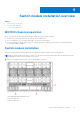
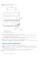

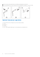
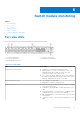
Table Of Contents
- MXG610s Fibre Channel Switch Module Installation Guide May 2021
- Contents
- About this guide
- Switch module overview
- Installation preparation
- Switch module installation overview
- Transceiver and cable installation
- Switch module monitoring
- Initial setup and verification
- Technical specifications
- Regulatory statements
- Caution and danger notices
- Dell EMC support

2. Orient the switch module port side facing you.
The module latch is on the right side.
1. Backplane connectors
2. Switch module top view.
3. Switch module latch in the open position.
3. Open the release lever, and slide the switch module into the slot completely.
You hear a click when the switch module is locked into the I/O module bay. If power is applied to the MX7000, locking the
switch module in the module bay powers on the switch.
When you apply power, the switch module runs POSTs which may take up to two minutes to complete. After the power/
status LED light is steady green for at least two minutes, the module is ready to use.
4. Start from port 0, then port 17, and then the rest of the ports when cabling the SFP+ ports.
You are now ready to insert more SFP+/QSFP optical transceivers, if needed. Be sure to use only Brocade-branded SFP+/QSFP
optical transceivers. The MXG610s does not recognize non-Broadcom products.
Switch module replacement
If there is a switch module failure, you must remove and replace the switch module.
NOTE:
Before beginning this procedure, you must have a replacement switch module or filler blade available. Never leave
the slot on the blade server chassis open for an extended time period. To maintain proper airflow, fill the slot with either a
replacement switch module or filler blank.
For more information about removing and replacing the switch module, see the PowerEdge MX7000 Users Guide.
1. Back up the switch module configuration to an FTP server using the configUpload command.
14
Switch module installation overview