
Install Guide

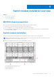
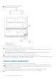

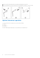
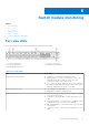
Table Of Contents
- MXG610s Fibre Channel Switch Module Installation Guide May 2021
- Contents
- About this guide
- Switch module overview
- Installation preparation
- Switch module installation overview
- Transceiver and cable installation
- Switch module monitoring
- Initial setup and verification
- Technical specifications
- Regulatory statements
- Caution and danger notices
- Dell EMC support

The configUpload command uploads the switch module configuration to the server and makes it available for
downloading to the replacement switch module if necessary. To ensure that a complete configuration is available for
downloading to a replacement switch module, back up the configuration regularly.
2. Stop all activity requiring the ports the switch module uses.
To verify that there is no activity, view the switch module LEDs.
3. Disconnect all cables from the SFP+/QSFP optical transceivers.
4. Remove the SFP+ or QSFP optical transceivers from the switch module external ports.
5. Press the release latch, and gently pull the release lever out from the switch module.
You can feel the switch module unseat and move out of the I/O module bay approximately 0.6 cm (0.25 in).
The following shows the open and unlocked view of the release lever and release latch:
a. Backplane connectors
b. Switch module top view
c. Switch module release lever and latch
6. Slide the switch module out of the I/O module bay and set it aside.
NOTE:
If you do not insert a replacement switch module, to maintain proper airflow and cooling, use a filler blank to fill
the empty slot. Do not leave the slot empty.
7. Insert the replacement switch module in the I/O module bay of the blade server chassis.
Complete this step within 60 seconds.
8. Insert the SFP+ or QSFP optical transceivers.
9. Reconnect the cables.
For more information, see the SFP+ or QSFP optical transceivers documentation.
Switch module installation overview
15