
Install Guide

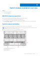
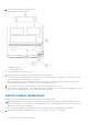

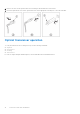
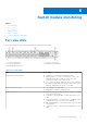
Table Of Contents
- MXG610s Fibre Channel Switch Module Installation Guide May 2021
- Contents
- About this guide
- Switch module overview
- Installation preparation
- Switch module installation overview
- Transceiver and cable installation
- Switch module monitoring
- Initial setup and verification
- Technical specifications
- Regulatory statements
- Caution and danger notices
- Dell EMC support

Table 4. Port-side LEDs (continued)
LED Description
● Slow flashing green, 2-second intervals—Online but
segmented; Loopback cable or incompatible switch.
● Fast flashing green, 1/2-second intervals—Internal
loopback, diagnostic.
● Flickering green—Online and frames flowing through the
port.
POST results
The power-on self-test (POST) system check performs each time you start up, reboot, or reset the switch module. During the
POST, the LEDs activate in various indicator patterns.
NOTE: The default POST diagnostic level is 0; therefore, no POST runs by default. To run the POST, set the POST
diagnostic level to a nonzero value before powering on the switch module.
To determine whether POST completed successfully or whether any errors were detected:
● Verify that the LEDs on the switch module indicate a healthy switch.
If one or more LEDs do not display a healthy state, verify that the LEDs are not set to beacon. To verify the LED state, use
the switchShow command or web Tools.
● To verify that the switch module is working correctly, use the blade server management application.
● Review the system log for errors.
Any errors detected during POST are written to the system log. This log is accessible through the errShow command.
BOOT results
BOOT includes the following tasks after POST completes:
● Performs universal port configuration
● Initializes links
● Analyzes the fabric. If any ports are connected to other switches, the switch participates in a fabric configuration.
● Obtains a domain ID and assigns port addresses.
● Constructs unicast routing tables.
● Enables normal port operation.
Diagnostic tests
In addition to the POST, the fabric OS includes diagnostic tests to help troubleshoot the hardware and firmware. These tests
include internal connections and circuitry, fixed media, and the transceivers and cables in use.
Initiate diagnostic tests with the command line using a secure shell (SSH) session or a terminal set up with a serial connection
to the switch. Some tests require the ports to connect by external cables to allow diagnostics to verify the serializer/deserializer
interface, transceivers, and cables. For information about the available diagnostic tests, use the diagHelp command.
All diagnostic tests are run at 32 Gbps link speeds.
NOTE: Diagnostic tests can temporarily lock the transmit and receive link speed.
● Off—No light or signal carrier; no module or cable for the media interface.
● Solid amber—Receiving light or signal carrier, but not yet online,
● Slow flashing amber, 2-second intervals—Disabled; the result of diagnostics or the portDisable command.
● Fast flashing amber, 1/2-second intervals—Error; a fault with a port.
20
Switch module monitoring