
Install Guide
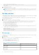
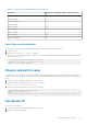
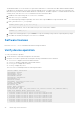
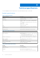
Table Of Contents
- MXG610s Fibre Channel Switch Module Installation Guide May 2021
- Contents
- About this guide
- Switch module overview
- Installation preparation
- Switch module installation overview
- Transceiver and cable installation
- Switch module monitoring
- Initial setup and verification
- Technical specifications
- Regulatory statements
- Caution and danger notices
- Dell EMC support

Technical specifications
This section highlights the features and specifications for the Dell EMC MXG610s 32 Gbps FC switch module.
System specifications
Table 6. System specifications
System components Description
Enclosure Less than 1U module—2.75 cm / 1.08 inches
Power inlet Internal to the chassis
Power supplies
12 V power supply from the Dell EMC PowerEdge MX7000
chassis
3.3 V standby power supply derived from 12 V source on the
switch module
Maximum power—150 Watts
Fans Internal to the chassis
Cooling Integrated system cooling; back-to-front port-side exhaust
System architecture Nonblocking shared memory switch
System processors Freescale PowerPC T1022E with two cores at 1.2 GHz
Table 7. Fibre Channel specifications
System components Description
Fibre Channel ports Default switch mode
● 16 external ports supporting 8 Gbps, 16 Gbps, and 32 Gbps
speeds using eight SFPs and two QSFPs
● 16 internal ports supporting 16 Gbps and 32 Gbps speeds
ANSI Fibre Channel protocol Fibre Channel Physical and Signaling Interface standard—FC-
PH
Modes of operation Fibre Channel Class 2, Class 3, and Class F
Fabric initialization Complies with FC-SW-5
FCIP—IP over Fibre Channel Complies with FC-IP 2.3 of FCA profile
Port status Bicolor LED—amber/green
Table 8. Default switch module settings
Setting Description
Switch name Dell EMC MXG610s
Default switch mode Access Gateway mode
IP address
Before factory restore defaults: 10.77.77.77
After factory restore defaults: 192.168.0.200+(SlotID[1~2])
8
30 Technical specifications