MXG610s Fibre Channel Switch Module Setup Guide Supporting fabric OS 8.1.0_Inx and 9.0.1a May 2021 Rev.
Notes, cautions, and warnings NOTE: A NOTE indicates important information that helps you make better use of your product. CAUTION: A CAUTION indicates either potential damage to hardware or loss of data and tells you how to avoid the problem. WARNING: A WARNING indicates a potential for property damage, personal injury, or death. © 2021 Dell Inc. or its subsidiaries. All rights reserved. Dell, EMC, and other trademarks are trademarks of Dell Inc. or its subsidiaries.
Contents Chapter 1: About this guide........................................................................................................... 4 Chapter 2: MXG610s Setup Guide..................................................................................................5 MX7000 chassis preparation............................................................................................................................................ 5 Switch module installation.........................................
1 About this guide This guide provides site preparation recommendations, step-by-step procedures for rack mounting and desk mounting, inserting modules, and connecting to a power source. CAUTION: To avoid electrostatic discharge (ESD) damage, wear grounding wrist straps when handling this equipment. NOTE: Only trained and qualified personnel can install this equipment. Read this guide before you install and power up this equipment. This equipment contains two power cords.
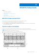
2 MXG610s Setup Guide Topics: • • • • • • • MX7000 chassis preparation Switch module installation Serial connection Optical transceivers and cabling installation Port-side LEDs Static IP addresses Additional country-specific IEEE notices MX7000 chassis preparation Before you insert the switch module in the MX7000 chassis, meet the following conditions: ● The chassis is powered up and meets all its specific power requirements. ● The I/O module bay C1 or C2 is empty and ready to receive the switch module.
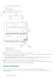
1. PowerEdge MX7000 chassis back view. 2. Switch module slot C2 3. Switch module slot C1 2. Orient the switch module port side facing you. The module latch is on the right side. 1. Backplane connectors 2. Switch module top view. 3. Switch module latch in the open position. 3. Open the release lever, and slide the switch module into the slot completely. You hear a click when the switch module is locked into the I/O module bay.
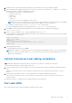
2. Disable any serial communication programs running on the workstation such as synchronization programs. 3. Open a terminal emulator application such as PuTTY, XShell, or SecureCRT on a Windows PC, or TERM, TIP, or C-Kermit in a LINUX environment.
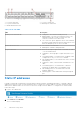
1. FC port 0 status LED 3. FC port 24 status LED 5. Module identification LED 2. FC port 17 status LED 4. Module power status LED Table 1. Port-side LEDs LED Description Module power and status LED ● Solid green—The switch is working correctly. ● Blinking amber—The switch is working incorrectly. The temperature may be too high, a software error has occurred, or another error is discovered. ● Off—There is no power supplied to the FC switch module.
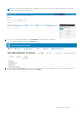
NOTE: You may also access the WebTools configuration UI to manage the switch module by typing the switch module IP address into any supported web browser. 3. Select the I/O module name, IP address, or View Details on the right side of the display. The Overview tab is displayed. Select the Settings tab. 4. Click and expand the Network option. Select the required check boxes, and complete the IPv4 or IPv6 settings, DNS server settings, and optionally the management VLAN ID. Click Apply.
5. Click and expand the Management option. Specify a hostname and root password. Click Apply. 6. Click and expand the Monitoring option. Select the Enable SNMP check box, the SNMP version, and enter a read community string. Click Apply.
7. Click and expand the Advanced Settings option. Select the needed check boxes. 8. Click Apply. You have configured the IP address and other settings for the switch module.
MXG610s Setup Guide
3 Dell EMC support The Dell EMC support site provides documents and tools to help you use Dell EMC equipment and mitigate network outages. Through the support site you can obtain technical information, access software upgrades and patches, download available management software, and manage your open cases. The Dell EMC support site provides integrated, secure access to these services. To access the Dell EMC support site, go to www.dell.com/support/.