
Install Guide

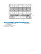
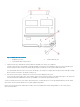
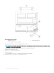
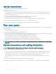

Figure 5. Switch module orientation
1
Backplane connectors 2 Switch module top view
3 Switch module latch in open position
3 Open the release lever, and slide the switch module into the blade server chassis slot completely.
You hear a click when the switch module is locked in the blade server chassis I/O module bay. If the power is on in the blade server
chassis, locking the switch module in the module bay provides power and turn-ons the switch module and the LEDs.
The switch module then runs POSTs. These tests can take up to two minutes to complete. After the power/status LED light is steady
green for at least two minutes, the module is ready to use.
4 Start from port 0, then port 17, and then the rest of the ports when cabling the SFP+ ports.
If you use QSFP ports instead of SFP+ ports, transfer the port license from port 0 and 17 to the desired QSFP ports. The QSFP ports
must be unused and no additional port licenses are available. Ports 0 and 17 are prelicensed at factory.
You are now ready to insert more SFP+/QSFP optical transceivers, if needed. Be sure to use only Brocade-branded SFP+/QSFP optical
transceivers. The FC switch module does not recognize unapproved products.
Before you insert the transceivers and attach the cables, review the installation precautions and guidelines for SFP+/QSFP optical
transceivers and cables.
16
Switch module installation overview