
Setup Guide

For instructions specic to a cable type, see the cable manufacturer’s documentation.
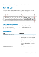
Port-side LEDs
Each switch module uses bicolored external LEDs to indicate operation status. After you
install the switch module in a blade server chassis I/O module, the LEDs become active.
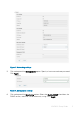
Figure 11. Switch module front panel LEDs
1 FC port 0 status LED 2 FC port 17 status LED
3 FC port 24 status LED 4 Module power status LED
5 Module identication LED
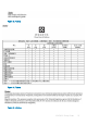
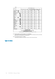
Table 1. Port-side LEDs
LED Description
Module power and status LED
• Solid green—The switch is working
correctly.
• Blinking amber—The switch is working
incorrectly. The temperature may be too
high, a software error has occurred, or
another error is discovered.
• O—There is no power supplied to the
FC switch module. Reseat the module
and ensure that the chassis power is on
and it has adequate power for the I/O
module.
Module identication LED
• O—Module is not identied.
MXG610s Setup Guide 13