
API Guide

ip route-import route-target
ip route-import 1:1
OS10(config)#interface ethernet 1/1/1
OS10(conf-if-eth1/1/1)# ip vrf forwarding VRF1
OS10(conf-if-eth1/1/1)# ip address 120.0.0.1/24
OS10(config)#interface ethernet 1/1/2
OS10(conf-if-eth1/1/2)# ip vrf forwarding VRF2
OS10(conf-if-eth1/1/2)# ip address 140.0.0.1/24
OS10(config)#ip route vrf VRF1 160.0.0.0/24 120.0.0.2
OS10(config)# ip vrf VRF1
OS10(conf-vrf)# ip route-export 1:1
OS10(config)# ip vrf VRF2
OS10(conf-vrf)# ip route-import 1:1
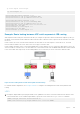
Example: Route leaking between VRFs with asymmetric IRB routing
With asymmetric IRB routing, the virtual networks that you configure are present in all the VXLAN tunnel endpoints (VTEPs). If
the DHCP server and client reside in different VRFs within the same or different VTEPs, request from the client does not reach
the server.
In this scenario, the server network must be leaked to the client VRF for the client request to reach the server. The client
network must be leaked to the server VRF for the server reply to reach the client.
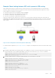
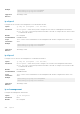
In this example, the DHCP client is connected to GREEN VRF in VTEP1 and the server is connected to RED VRF in VTEP 2. The
client is not able to reach the server. The client and server connected networks from the GREEN and RED VRFs must be leaked
to the other tenant VRFs respectively. Route leaking enables server connectivity for hosts connected to different VRFs.
Figure 8. Route leaking between VRFs with asymmetric IRB routing
For VXLAN-related configurations, see Configure VXLAN. To configure route leaking between VRFs with asymmetric IRB
routing:
VTEP1
1. Configure IP helper address specifying the DHCP server ip address in the client-connected virtual networks with the client-
connected VRF name. For IPv6 DHCP helper address, specify the server VRF in the helper-address command.
VTEP1(config)# interface virtual-network 10
VTEP1(conf-if-vn-10)# ip helper-address 20.1.1.100 vrf GREEN
Layer 3
541