
API Guide

VLT configuration
1. Create a VLT domain, and configure VLTi.
OS10(config)# interface range ethernet 1/1/4-1/1/5
OS10(conf-range-eth1/1/4-1/1/5)# no switchport
OS10(conf-range-eth1/1/4-1/1/5)# exit
OS10(config)# vlt-domain 1
OS10(conf-vlt-1)# discovery-interface ethernet 1/1/4-1/1/5
2. Configure a VLT MAC address.
OS10(conf-vlt-1)# vlt-mac 12:5e:23:f4:23:54
3. Specify the management IP address of the VLT peer as a backup link.
OS10(conf-vlt-1)# backup destination 10.10.10.1
4. Configure VLT port channels.
SW2-to-VM VLT port channel configuration
OS10(config)# interface port-channel 10
OS10(conf-if-po-10)# description SW2ToVM
OS10(conf-if-po-10)# vlt-port-channel 10
OS10(conf-if-po-10)# switchport mode trunk
OS10(conf-if-po-10)# switchport trunk allowed vlan 100,200
OS10(conf-if-po-10)# exit
OS10(config)# interface ethernet 1/1/2-1/1/3
OS10(conf-if-eth1/1/2-1/1/3)# no shutdown
OS10(conf-if-eth1/1/2-1/1/3)# channel-group 10
( Optional) Peer routing configuration
● Configure peer routing.
OS10(config)# vlt-domain 1
OS10(conf-vlt-1)# peer-routing
PBR configuration
Apply the policy on the VLTi interfaces of both VLT peers.
OS10(config)# ip access-list PBR-A2C
OS10(conf-ipv4-acl)# permit ip 10.10.10.0/24 any
OS10(conf-route-map)# route-map Map1
OS10(conf-route-map)# match ip address PBR-A2C
OS10(conf-route-map)# set ip next-hop 10.10.20.10
OS10(conf-route-map)# exit
OS10(config)# interface ethernet 1/1/4-1/1/6
OS10(conf-if-eth1/1/4-1/1/6)# ip policy route-map Map1
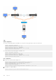
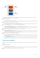
Sample configuration
Consider a scenario where traffic from source IP address 1.1.1.1 ingresses through VLAN40 that is part of VRF RED. The egress
interface for this traffic is also on the same VRF RED with IP address 4.4.4.4, as shown.
756
Layer 3