
API Guide
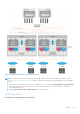
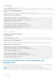

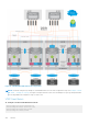
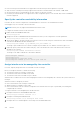

Figure 17. VXLAN BGP EVPN with centralized L3 gateway
NOTE:
This centralized L3 gateway example for VXLAN BGP EVPN uses the same configuration steps as in Example:
VXLAN BGP EVPN — Multiple AS topology. Configure each spine and leaf switch as in the Multiple AS topology example,
except:
● Because VTEPs 1 and 2 operate only in Layer 2 VXLAN mode, do not configure IP switching in the overlay network.
This step consists of configuring virtual network interfaces with IP addresses, anycast IP addresses, and anycast
gateway MAC addresses.
● Configure IP switching in the overlay network only on VTEPs 3 and 4.
VTEP 3 Leaf Switch
14. Configure IP switching in the overlay network
VXLAN
983