
Users Guide
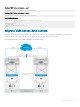

Virtual link trunking
Virtual link trunking (VLT) is a Layer 2 (L2) aggregate protocol between end devices (servers) connected to dierent network devices. VLT
reduces the role of spanning tree protocols (STPs) by allowing link aggregation group (LAG) terminations on two separate distribution or
core switches and supporting a loop-free topology.
• Allows a single device to use a LAG across two upstream devices
• Provides a loop-free topology
• Eliminates STP-blocked ports
• Optimizes the use of all available uplink bandwidth
• Guarantees fast convergence if either a link or a device fails
• Enhances optimized forwarding with virtual router redundancy protocol (VRRP)
• Provides link-level resiliency
• Assures high availability
VLT provides L2 multipathing, creating redundancy through increased bandwidth, enabling multiple parallel paths between nodes and load-
balancing trac where alternative paths exist.
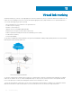
VLT presents a single logical L2 domain from the perspective of attached devices that have a virtual link trunk terminating on a separate
node in the VLT domain. The two VLT nodes are independent Layer2 or Layer3 (L2/L3) switches for devices in the upstream network.
L2/L3 control plane protocols and system management features function normally in VLT mode.
To ensure the same behavior on both sides of the VLT nodes, VRRP requires state information coordination. VLT congurations must be
identical on both sides of a trunk. External switches or servers with LACP see the VLT switches as a single virtual switch.
11
622 Virtual link trunking