
Owners Manual


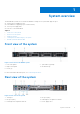
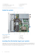

Table Of Contents
- PowerVault NX440 Network Attached Storage System Installation and Service Manual
- Contents
- System overview
- Technical specifications
- Initial system setup and configuration
- Reinstalling the operating system using a DVD
- Diagnostics and indicators
- Pre-operating system management applications
- System Setup
- Viewing System Setup
- System Setup details
- System BIOS
- Viewing System BIOS
- System BIOS Settings details
- System Information
- Viewing System Information
- System Information details
- Memory Settings
- Viewing Memory Settings
- Memory Settings details
- Processor Settings
- Viewing Processor Settings
- Processor Settings details
- SATA Settings
- Viewing SATA Settings
- SATA Settings details
- Boot Settings
- Viewing Boot Settings
- Boot Settings details
- Integrated Devices
- Viewing Integrated Devices
- Integrated Devices details
- Serial Communication
- Viewing Serial Communication
- Serial Communication details
- System Profile Settings
- Viewing System Profile Settings
- System Profile Settings details
- System Security
- Viewing System Security
- System Security Settings details
- Creating a system and setup password
- Using your system password to secure your system
- Deleting or changing system and setup password
- Operating with setup password enabled
- Redundant OS Control
- Viewing Redundant OS Control
- Redundant OS Control screen details
- Miscellaneous Settings
- Viewing Miscellaneous Settings
- Miscellaneous Settings details
- iDRAC Settings utility
- Device Settings
- Dell Lifecycle Controller
- Boot Manager
- PXE boot
- System Setup
- Jumpers and connectors
- Installing and removing system components
- Safety instructions
- Before working inside your system
- After working inside your system
- Front bezel
- Hard Drives
- System cover
- Cooling fans
- Intrusion switch
- System memory
- Expansion cards and expansion card riser
- Storage controller card
- Replacing the system battery
- Replacing the optional internal USB memory key
- Optical drive
- Processor and heat sink
- Drive backplane
- Power supply unit
- Power distribution board
- System board
- Trusted Platform Module
- Control panels
- Getting help
- Documentation resources

7. Power supply unit 2 8. System identification button
9. System status indicator cable port (CMA) 10. USB 3.0 port (2)
11. iDRAC9 dedicated network port 12. VGA port
For more information about the ports and connectors, see Technical specifications.
Inside the system
Figure 3. Inside the system
1.
Intrusion switch 2. Optical drive
3. Power distribution board 4. PERC card
5. Expansion card riser 6. Heat sink
7. Memory module sockets 8. System board
9. Fan (4) 10. Drive backplane
Locating the information tag of your system
A unique Express Service Code and Service Tag provides specific information about the system. Pull out the information tag
located in front of the system to view the Express Service Code and Service Tag. Alternatively, the information may be on a
sticker on the back of the system chassis. The mini Enterprise Service Tag (EST) is found on the back of the system chassis.
Dell support uses this information to route support calls to the appropriate personnel.
8
System overview