
Administrator Guide
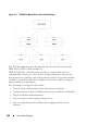
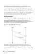
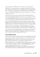
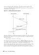
Table Of Contents
- Introduction
- Switch Feature Overview
- System Management Features
- Multiple Management Options
- System Time Management
- Log Messages
- Integrated DHCP Server
- Management of Basic Network Information
- IPv6 Management Features
- Dual Software Images
- File Management
- Switch Database Management Templates
- Automatic Installation of Firmware and Configuration
- sFlow
- SNMP Alarms and Trap Logs
- CDP Interoperability Through ISDP
- Remote Monitoring (RMON)
- N3000 Series Advanced and Advanced-Lite Firmware Images
- Stacking Features
- Security Features
- Configurable Access and Authentication Profiles
- Password-Protected Management Access
- Strong Password Enforcement
- TACACS+ Client
- RADIUS Support
- SSH/SSL
- Inbound Telnet Control
- Denial of Service
- Port Protection
- Captive Portal
- 802.1X Authentication (IEEE 802.1X)
- MAC-Based 802.1X Authentication
- 802.1X Monitor Mode
- MAC-Based Port Security
- Access Control Lists (ACLs)
- Time-Based ACLs
- IP Source Guard (IPSG)
- DHCP Snooping
- Dynamic ARP Inspection
- Protected Ports (Private VLAN Edge)
- Green Technology Features
- Power over Ethernet (PoE) Plus Features
- Key PoE Plus Features for the Dell EMC Networking N1108P-ON, N1124P-ON, N1148P-ON, N2024P, N2048P, N2128PX-ON, N3024P, N3048P, and N3132PX-ON Switches
- Power Over Ethernet (PoE) Plus Configuration
- PoE Plus Support
- PoE 60W Support
- Powered Device Detection
- PoE Power Management Modes
- Power Management in Guard Band
- PoE Plus Default Settings
- Switching Features
- Flow Control Support (IEEE 802.3x)
- Head of Line Blocking Prevention
- Alternate Store and Forward (ASF)
- Jumbo Frames Support
- Auto-MDI/MDIX Support
- VLAN-Aware MAC-based Switching
- Back Pressure Support
- Auto-negotiation
- Storm Control
- Port Mirroring
- Static and Dynamic MAC Address Tables
- Link Layer Discovery Protocol (LLDP)
- Link Layer Discovery Protocol (LLDP) for Media Endpoint Devices
- Connectivity Fault Management (IEEE 802.1ag)
- Priority-based Flow Control (PFC)
- Data Center Bridging Exchange (DBCx) Protocol
- Enhanced Transmission Selection
- Cisco Protocol Filtering
- DHCP Layer-2 Relay
- Virtual Local Area Network Supported Features
- Spanning Tree Protocol Features
- Link Aggregation Features
- Routing Features
- Address Resolution Protocol (ARP) Table Management
- VLAN Routing
- IP Configuration
- Open Shortest Path First (OSPF)
- Border Gateway Protocol (BGP)
- Virtual Routing and Forwarding (VRF)
- BOOTP/DHCP Relay Agent
- IP Helper and DHCP Relay
- Routing Information Protocol
- Router Discovery
- Routing Table
- Virtual Router Redundancy Protocol (VRRP)
- Tunnel and Loopback Interfaces
- IPv6 Routing Features
- Quality of Service (QoS) Features
- Layer-2 Multicast Features
- Layer-3 Multicast Features
- System Management Features
- Hardware Overview
- Dell EMC Networking N1100-ON Series Switch Hardware
- Dell EMC Networking N1500 Series Switch Hardware
- Dell EMC Networking N2000 Series Switch Hardware
- Dell EMC Networking N2100-ON Series Switch Hardware
- Dell EMC Networking N3000 Series Switch Hardware
- Dell EMC Networking N3100-ON Series Switch Hardware
- Dell EMC Networking N4000 Series Switch Hardware
- Switch MAC Addresses
- Using Dell EMC OpenManage Switch Administrator
- Using the Command-Line Interface
- Default Settings
- Setting the IP Address and Other Basic Network Information
- Managing QSFP Ports
- Stacking
- Stacking Overview
- Dell EMC Networking N1124-ON/N1148-ON, N1500, N2000, N2100-ON, N3000, N3048EP-ON, N3100-ON, and N4000 Stacking Compatibility
- How is the Stack Master Selected?
- Adding a Switch to the Stack
- Removing a Switch from the Stack
- How is the Firmware Updated on the Stack?
- What is Stacking Standby?
- What is Nonstop Forwarding?
- Switch Stack MAC Addressing and Stack Design Considerations
- NSF Network Design Considerations
- Why is Stacking Needed?
- Default Stacking Values
- Managing and Monitoring the Stack (Web)
- Managing the Stack (CLI)
- Stacking and NSF Usage Scenarios
- Stacking Overview
- Authentication, Authorization, and Accounting
- AAA Introduction
- Authentication
- Authorization
- Accounting
- IEEE 802.1X
- What is IEEE 802.1X?
- What are the 802.1X Port Authentication Modes?
- What is MAC-Based 802.1X Authentication?
- What is the Role of 802.1X in VLAN Assignment?
- What is Monitor Mode?
- How Does the Authentication Server Assign DiffServ Policy?
- What is the Internal Authentication Server?
- Default 802.1X Values
- Configuring IEEE 802.1X (Web)
- Captive Portal
- Monitoring and Logging System Information
- System Monitoring Overview
- Default Log Settings
- Monitoring System Information and Configuring Logging (Web)
- Device Information
- System Health
- System Resources
- Unit Power Usage History
- Integrated Cable Test for Copper Cables
- Optical Transceiver Diagnostics
- Log Global Settings
- RAM Log
- Log File
- SYSLOG Server
- Email Alert Global Configuration
- Email Alert Mail Server Configuration
- Email Alert Subject Configuration
- Email Alert To Address Configuration
- Email Alert Statistics
- Monitoring System Information and Configuring Logging (CLI)
- Logging Configuration Examples
- Managing General System Settings
- System Settings Overview
- Default General System Information
- Configuring General System Settings (Web)
- System Information
- CLI Banner
- SDM Template Preference
- Clock
- SNTP Global Settings
- SNTP Authentication
- SNTP Server
- Summer Time Configuration
- Time Zone Configuration
- Card Configuration
- Slot Summary
- Supported Cards
- Power Over Ethernet Global Configuration
- Power Over Ethernet Unit Configuration
- Power Over Ethernet Interface Configuration
- Configuring System Settings (CLI)
- Configuring System Information
- Configuring the Banner
- Managing the SDM Template
- Configuring SNTP Authentication and an SNTP Server
- Setting the System Time and Date Manually
- Configuring the Expansion Slots (Dell EMC Networking N3000/N3100-ON/N4000 Series Only)
- Viewing Slot Information (Dell EMC Networking N4000 Series Only)
- Configuring PoE Settings (Dell EMC Networking N1108P-ON/ N1124P-ON/ N1148P-ON, N1524P/N1548P, N2024P/N2048P/N2128PX-ON, N3024P/N3048P/N3048EP-ON/N3132PX-ON Only)
- General System Settings Configuration Examples
- SNMP
- Images and File Management
- DHCP and USB Auto-Configuration
- Auto Configuration Overview
- What Is USB Auto Configuration?
- What Files Does USB Auto Configuration Use?
- How Does USB Auto Configuration Use the Files on the USB Device?
- What Is the Setup File Format?
- What Is the DHCP Auto Configuration Process?
- Monitoring and Completing the DHCP Auto Configuration Process
- What Are the Dependencies for DHCP Auto Configuration?
- Default Auto Configuration Values
- Managing Auto Configuration (Web)
- Managing Auto Configuration (CLI)
- Auto Configuration Example
- Auto Configuration Overview
- Monitoring Switch Traffic
- Traffic Monitoring Overview
- Default Traffic Monitoring Values
- Monitoring Switch Traffic (Web)
- sFlow Agent Summary
- sFlow Receiver Configuration
- sFlow Sampler Configuration
- sFlow Poll Configuration
- Interface Statistics
- Etherlike Statistics
- GVRP Statistics
- EAP Statistics
- Utilization Summary
- Counter Summary
- Switchport Statistics
- RMON Statistics
- RMON History Control Statistics
- RMON History Table
- RMON Event Control
- RMON Event Log
- RMON Alarms
- Port Statistics
- LAG Statistics
- Port Mirroring
- Monitoring Switch Traffic (CLI)
- Traffic Monitoring Examples
- iSCSI Optimization
- iSCSI Optimization Overview
- What Does iSCSI Optimization Do?
- What Occurs When iSCSI Optimization Is Enabled or Disabled?
- How Does the Switch Detect iSCSI Traffic Flows?
- How Is Quality of Service Applied to iSCSI Traffic Flows?
- How Does iSCSI Optimization Use ACLs?
- What Information Does the Switch Track in iSCSI Traffic Flows?
- How Does iSCSI Optimization Interact With Dell EqualLogic and Compellant Arrays?
- How Does iSCSI Optimization Interact with Other SAN Arrays?
- How Does iSCSI Optimization Interact with DCBx?
- iSCSI CoS and Priority Flow Control/Enhanced Transmission Selection Interactions
- Default iSCSI Optimization Values
- Configuring iSCSI Optimization (Web)
- Configuring iSCSI Optimization (CLI)
- iSCSI Optimization Configuration Examples
- iSCSI Optimization Overview
- Port Characteristics
- Port and System Security
- Access Control Lists
- VLANs
- VLAN Overview
- Default VLAN Behavior
- Configuring VLANs (Web)
- Configuring VLANs (CLI)
- Creating a VLAN
- Configuring VLAN Settings for a LAG
- Configuring Double VLAN Tagging
- Configuring MAC-Based VLANs
- Configuring IP-Based VLANs
- Configuring a Protocol-Based VLAN
- Configuring GVRP
- Configuring Voice VLANs
- Configuring a Voice VLAN (Extended Example)
- Enterprise Voice VLAN Configuration With QoS
- MLAG with RPVST and Voice VLAN
- Assigning an 802.1p Priority to VLAN Traffic
- Configuring a Private VLAN
- VLAN Configuration Examples
- Spanning Tree Protocol
- Discovering Network Devices
- Port-Based Traffic Control
- Layer-2 Multicast Features
- L2 Multicast Overview
- Snooping Switch Restrictions
- Default L2 Multicast Values
- Configuring L2 Multicast Features (Web)
- Multicast Global Parameters
- Bridge Multicast Group
- MFDB Summary
- MRouter Status
- General IGMP Snooping
- Global Querier Configuration
- VLAN Querier
- VLAN Querier Status
- MFDB IGMP Snooping Table
- MLD Snooping General
- MLD Snooping Global Querier Configuration
- MLD Snooping VLAN Querier
- MLD Snooping VLAN Querier Status
- MFDB MLD Snooping Table
- MVR Global Configuration
- MVR Members
- MVR Interface Configuration
- MVR Statistics
- GARP Timers
- GMRP Parameters
- MFDB GMRP Table
- Configuring L2 Multicast Features (CLI)
- Case Study on a Real-World Network Topology
- Connectivity Fault Management
- Snooping and Inspecting Traffic
- Traffic Snooping and Inspection Overview
- Default Traffic Snooping and Inspection Values
- Configuring Traffic Snooping and Inspection (Web)
- DHCP Snooping Configuration
- DHCP Snooping Interface Configuration
- DHCP Snooping VLAN Configuration
- DHCP Snooping Persistent Configuration
- DHCP Snooping Static Bindings Configuration
- DHCP Snooping Dynamic Bindings Summary
- DHCP Snooping Statistics
- IPSG Interface Configuration
- IPSG Binding Configuration
- IPSG Binding Summary
- DAI Global Configuration
- DAI Interface Configuration
- DAI VLAN Configuration
- DAI ACL Configuration
- DAI ACL Rule Configuration
- DAI Statistics
- Configuring Traffic Snooping and Inspection (CLI)
- Traffic Snooping and Inspection Configuration Examples
- Link Aggregation
- Data Center Bridging Features
- MAC Addressing and Forwarding
- DHCP Server Settings
- IP Routing
- Routing Interfaces
- Layer-2 and Layer-3 Relay Features
- OSPF and OSPFv3
- OSPF Overview
- OSPF Feature Details
- Default OSPF Values
- Configuring OSPF Features (Web)
- OSPF Configuration
- OSPF Area Configuration
- OSPF Stub Area Summary
- OSPF Area Range Configuration
- OSPF Interface Statistics
- OSPF Interface Configuration
- OSPF Neighbor Table
- OSPF Neighbor Configuration
- OSPF Link State Database
- OSPF Virtual Link Configuration
- OSPF Virtual Link Summary
- OSPF Route Redistribution Configuration
- OSPF Route Redistribution Summary
- NSF OSPF Configuration
- Configuring OSPFv3 Features (Web)
- OSPFv3 Configuration
- OSPFv3 Area Configuration
- OSPFv3 Stub Area Summary
- OSPFv3 Area Range Configuration
- OSPFv3 Interface Configuration
- OSPFv3 Interface Statistics
- OSPFv3 Neighbors
- OSPFv3 Neighbor Table
- OSPFv3 Link State Database
- OSPFv3 Virtual Link Configuration
- OSPFv3 Virtual Link Summary
- OSPFv3 Route Redistribution Configuration
- OSPFv3 Route Redistribution Summary
- NSF OSPFv3 Configuration
- Configuring OSPF Features (CLI)
- Configuring OSPFv3 Features (CLI)
- OSPF Configuration Examples
- Configuring OSPF VRFs
- VRF
- RIP
- VRRP
- BGP
- Overview
- BGP Operations
- Decision Process Overview
- Path Attributes
- BGP Finite State Machine (FSM)
- Detecting Loss of Adjacency
- Authentication
- Outbound Update Groups
- Removing Private AS Numbers
- Templates
- Resolving Interface Routes
- Originating BGP Routes
- Equal Cost Multipath (ECMP)
- BGP Next-Hop Resolution
- Address Aggregation
- Routing Policy
- Inbound Policy
- Outbound Policy
- Routing Policy Changes
- BGP Timers
- Communities
- Routing Table Overflow
- Route Reflection
- VRF Support
- BGP Neighbor Configuration
- Extended Communities
- VPNv4/VRF Route Distribution via MP-BGP
- IPv6
- BGP Limitations
- BGP Configuration Examples
- Bidirectional Forwarding Detection
- IPv6 Routing
- DHCPv6 Server Settings
- Differentiated Services
- Class-of-Service
- Auto VoIP
- IPv4 and IPv6 Multicast
- L3 Multicast Overview
- Default L3 Multicast Values
- Configuring General IPv4 Multicast Features (Web)
- Configuring IPv6 Multicast Features (Web)
- Configuring IGMP and IGMP Proxy (Web)
- Configuring MLD and MLD Proxy (Web)
- MLD Global Configuration
- MLD Routing Interface Configuration
- MLD Routing Interface Summary
- MLD Routing Interface Cache Information
- MLD Routing Interface Source List Information
- MLD Traffic
- MLD Proxy Configuration
- MLD Proxy Configuration Summary
- MLD Proxy Interface Membership Information
- Detailed MLD Proxy Interface Membership Information
- Configuring PIM for IPv4 and IPv6 (Web)
- Configuring DVMRP (Web)
- Configuring L3 Multicast Features (CLI)
- Configuring and Viewing IPv4 Multicast Information
- Configuring and Viewing IPv6 Multicast Route Information
- Configuring and Viewing IGMP
- Configuring and Viewing IGMP Proxy
- Configuring and Viewing MLD
- Configuring and Viewing MLD Proxy
- Configuring and Viewing PIM-DM for IPv4 Multicast Routing
- Configuring and Viewing PIM-DM for IPv6 Multicast Routing
- Configuring and Viewing PIM-SM for IPv4 Multicast Routing
- Configuring and Viewing PIM-SM for IPv6 Multicast Routing
- Configuring and Viewing DVMRP Information
- L3 Multicast Configuration Examples
- Audio Video Bridging
- OpenFlow
- Dell EMC Networking Python Support
- Appendix
- Index

Audio Video Bridging 1675
field in the SYNC and FOLLOW_UP messages. The master sends the
FOLLOW_UP message with the same sequence ID as the SYNC message.
The value (t2 – t1) gives the (offset + link delay) between the master and
slave. The link delay is calculated as described below. Assuming that the link
delay is symmetric, the offset value can be derived from (t2 – t1). This
sequence of SYNC and FOLLOW_UP messages is repeated at every SYNC
transmission interval.
A slave device can, in turn, act as a master for the downstream nodes by
forwarding incoming synchronization information to the downstream nodes.
The received SYNC/FOLLOW_UP messages are not forwarded as-is; a new
set of SYNC/FOLLOW_UP messages is generated based on the downstream
master port properties (port identity, port sequence ID, etc.). Also, the
correction field in the FOLLOW_UP packet is updated with the residence
time before transmitting the message on master port(s). The rate at which
SYNC messages are transmitted from the master port is limited. For example,
if SYNC messages are received on a bridge's slave port at a very high rate, the
SYNC messages are transmitted out of the bridge's master port at a rate
greater than or equal to one half of its configured SYNC interval. Ideally a
SYNC message is transmitted from a master port whenever a SYNC message
is received on its slave port. If a bridge acts as a grandmaster, SYNC messages
are generated based on the CPU clock speed; however, the rate at which
SYNC messages are transmitted out of the master interface is always greater
than or equal to half of the configured SYNC interval.
Link Delay Measurement
The peer delay mechanism measures the port-to-port propagation time (link
delay) between two ports. A delay measurement is made on all ports and can
be initiated independently of the 802.1AS port state. The transmission of
PDELAY_REQ message is the first step in the measurement process. The
delay requestor captures the time stamp of the transmission time of
PDELAY_REQ packet (t1). When the PDELAY_REQ message is received by
the delay responder, the packet's RX time stamp is captured (t2). The delay
responder issues two packets in response to the PDELAY_REQ: a delay
response PDELAY_RESP and a delay response follow up
PDELAY_RESP_FOLLOWUP. The receive timestamp of PDELAY_REQ
(t2) and transmit timestamp of PDELAY_RESP (t3) is captured and is