Dell EMC PowerVault ME4 Series Storage System Owner’s Manual July 2021 Rev.
Notes, cautions, and warnings NOTE: A NOTE indicates important information that helps you make better use of your product. CAUTION: A CAUTION indicates either potential damage to hardware or loss of data and tells you how to avoid the problem. WARNING: A WARNING indicates a potential for property damage, personal injury, or death. © 2018 – 2021 Dell Inc. or its subsidiaries. All rights reserved. Dell, EMC, and other trademarks are trademarks of Dell Inc. or its subsidiaries.
Contents Chapter 1: Storage system hardware............................................................................................. 5 Locate the service tag....................................................................................................................................................... 5 Enclosure configurations...................................................................................................................................................
Chapter 3: Module removal and replacement............................................................................... 42 ESD precautions................................................................................................................................................................ 42 Dealing with hardware faults.......................................................................................................................................... 43 Firmware updates.......................
1 Storage system hardware This chapter describes the front-end and back-end components of ME4 Series enclosures. Some of the modules within the enclosure are replaceable as described in Module removal and replacement on page 42. The types of modules and other components that can be replaced are defined below: ● CRU: Customer-replaceable Unit ● FRU: Field-replaceable Unit (requires service expertise) The terms CRU and FRU are used throughout this document.
a vertical orientation within the disk drawer. Two vertically-stacked drawers each hold 42 disks. If used, 2.5" disks require 3.5" adapters. These same chassis form factors are used for the supported expansion enclosures; but with I/O modules instead of controller modules. The 2U12 and 2U24 enclosures support single or dual-controller module configurations, but the 5U84 enclosure only supports a dual-controller module configuration.
Enclosure management The enclosure is mechanically and electrically compliant with the Storage Bridge Bay (SBB) v 2.1 specification. SBB modules actively manage the enclosure. Each module has a SAS expander with its own storage enclosure processor (SEP) that provides a SES target for a host to interface to, through the ANSI SES (SCSI Enclosure Services) standard. If one of these modules fails, the other module continues to operate.
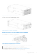
Figure 2. 2U12 enclosure system—rear orientation Figure 3. 2U24 enclosure system—front orientation The 2U24 controller enclosure is equipped with dual-controllers. Figure 4.
Figure 5. 5U84 enclosure system—front orientation The 5U84 controller enclosure is equipped with dual-controllers. Figure 6. 5U84 enclosure system—rear orientation Attach or remove the front bezel of a 2U enclosure The following figure shows a partial view of a 2U12 enclosure: Figure 7. Attaching or removing the 2U enclosure front bezel To attach the front bezel to the 2U enclosure: 1. 2. 3. 4. Locate the bezel, and while grasping it with your hands, face the front panel of the 2U12 or 2U24 enclosure.
NOTE: See Enclosure variants for details about various enclosure options. Enclosure variants The 2U chassis can be configured as a controller enclosure ME4012/ME4024, or an expansion enclosure ME412/ME424 as shown in 2U12 enclosure variants and 2U24 enclosure variants. The 5U chassis can be configured as a controller enclosure ME4084 or an expansion enclosure ME484 as shown in 5U84 enclosure variants.
Table 3. 5U84 enclosure variants Product Configuration PSUs 1 FCMs 2 Controller modules and IOMs 3 ME4084 12 Gb/s direct dock SFF SAS 2 5 2 ME484 12 Gb/s direct dock SFF SAS 2 5 2 1 Redundant PCMs must be compatible modules of the same type (both AC). 2 The fan control module (FCM) is a separate CRU (not integrated into a PCM). 3 Supported controller modules include 4-port FC/iSCSI, 4-port HD mini-SAS, and 4-port iSCSI 10Gbase-T.
2U enclosure rear panel Alphabetic designators on controller modules or IOMs and numeric designators on PCMs indicate slot sequencing for the modules used in 2U enclosures. Controller modules, IOMs, and PCMs are available as CRUs. The ME4 Series RBODs use 4-port controller modules. These RBODs support the ME412/ME424/ME484 EBODs for optionally adding storage. Figure 10. 2U controller enclosure—rear panel components (4-port FC/iSCSI) 1. Power cooling module slot 0 3. Controller module slot A 2.
2U rear panel components This section describes the controller module, expansion enclosure IOM, and power cooling module components. Controller module The top slot for holding controller modules is designated slot A and the bottom slot is designated slot B. The face plate details of the controller modules show the modules aligned for use in slot A. In this orientation, the controller module latch shown at the bottom of the module and it is in a closed/locked position.
Figure 16. 4-port mini-SAS HD controller module detail 1. 3. 5. 7. Back-end expansion SAS port USB serial port (CLI) 3.5 mm serial ports (service only) SAS ports (ports 3, 2, 1, 0) 2. Ethernet port used by management interfaces 4. 3.5 mm serial port (CLI) 6. Reset button Expansion enclosure IOM The following figure shows the IOM used in supported expansion enclosures for adding storage. Ports A/B/C ship configured with 12 Gb/s mini-SAS HD (SFF-8644) external connectors. Figure 17.
Figure 18. Power cooling module (PCM) 1. 3. 5. 7. PCM OK LED (Green) Fan Fail LED (Amber/blinking amber) On/Off switch Release latch 2. AC Fail LED (Amber/blinking amber) 4. DC Fail LED (Amber/blinking amber) 6. Power connector LED behavior: ● If any of the PCM LEDs are illuminated amber, a module fault condition or failure has occurred. ● For a detailed description of PCM LED behavior, see 2U enclosure LEDs on page 33.
5U84 enclosure front panel Figure 19. 5U84 enclosure—front panel components 1. 5U84 enclosure drawer (slot 0 = top drawer) 2. 5U84 enclosure drawer (slot 1 = bottom drawer) This figure shows a plan view of an enclosure drawer that is accessed from the enclosure front panel. The conceptual graphics are simplified for clarity. NOTE: See 5U84 enclosure DDIC LEDs on page 37 for 5U84 (LFF disks) DDIC LED behavior. Figure 20. 5U84 enclosure system - plan view of drawer accessed from front panel 1.
Figure 21. 5U84 controller enclosure—rear panel components (4-port FC/iSCSI) 1. 3. 5. 7. 9. Controller module slot A FCM slot 0 FCM slot 2 FCM slot 4 PSU slot 1 2. 4. 6. 8. Controller module slot B FCM slot 1 FCM slot 3 PSU slot 0 Figure 22. 5U84 controller enclosure—rear panel components (4-port SAS) 1. 3. 5. 7. 9. Controller module slot A FCM slot 0 FCM slot 2 FCM slot 4 PSU slot 1 2. 4. 6. 8.
Figure 23. 5U84 controller enclosure—rear panel components (4-port iSCSI 10Gbase-T) 1. 3. 5. 7. 9. Controller module slot A FCM slot 0 FCM slot 2 FCM slot 4 PSU slot 1 2. 4. 6. 8. Controller module slot B FCM slot 1 FCM slot 3 PSU slot 0 Figure 24. 5U84 expansion enclosure—rear panel components 1. 3. 5. 7. 9. IOM slot A FCM slot 0 FCM slot 2 FCM slot 4 PSU slot 1 2. 4. 6. 8.
Expansion module The 5U84 expansion enclosure uses the same IOMs that are used by 2U12 and 2U24 enclosures. Power supply module This figure shows the power supply unit that is used in 5U controller enclosures and optional 5U84 expansion enclosures. Figure 25. Power supply unit (PSU) 1. 3. 5. 7. Module release latch PSU Fault LED (Amber/blinking amber) Power OK LED (Green) Power switch 2. Handle 4. AC Fail LED (Amber/blinking amber) 6.
5U84 enclosure chassis The 5U84 enclosure includes the following features: ● 5U84 chassis configured with up to 84 LFF disks in DDICs. See 5U84 enclosure system - plan view of drawer accessed from front panel on page 16. ● 5U84 chassis configured with SFF disks in 2.5" to 3.5" hybrid driver carrier adapter. ● 5U84 empty chassis with midplane, module runner system, and drawers.
Figure 27. Drawer bezel details 1. 3. 5. 7. 9. Left side Anti-tamper lock Drawer fault Cable fault Drawer pull handle 2. 4. 6. 8. Right side Sideplane OK/Power Good Logical fault Drawer activity NOTE: For descriptions of drawer LED behavior, see Drawer LED states on page 37. Operator (Ops) panel LEDs Each ME4 Series enclosure features an Ops panel located on the chassis left ear flange. This section describes the Ops panel for 2U and 5U enclosures.
Table 4. Ops panel functions (continued) No. Indicator Status 3 Unit identification display (UID) Green (seven-segment display: enclosure sequence) 4 Identity ● Blinking blue (0.25 Hz): system ID locator is activated ● Off: Normal state System power LED (green) LED displays green when system power is available. LED is off when system is not operating. Status/Health LED (blue/amber) LED illuminates constant blue when the system is powered on and functioning normally.
Table 5. Ops panel functions (continued) No. Indicator Status 4 Logical status Constant or blinking amber: fault present 5 Top drawer fault Constant or blinking amber: fault present in drive, cable, or sideplane 6 Bottom drawer fault Constant or blinking amber: fault present in drive, cable, or sideplane Unit identification display The UID is a dual seven-segment display that shows the numerical position of the enclosure in the cabling sequence. This is also called the enclosure ID.
Each controller module maintains VPD (Vital Product Data) in EEPROM devices. In a dual-controller module system, controller modules are interconnected by SBB-defined I2C buses on the midplane. In this way, the SBB module can discover the type and capabilities of the partner SBB module, and vice versa, within the enclosure.
Table 6. ME4 Series controller modules (FC and iSCSI SFPs) LEDs (continued) LED Description Definition ● Off—In a working controller, cache is clean (contains no unwritten data). This is an occasional condition that occurs while the system is booting. ● Blinking green—A CompactFlash flush or cache self-refresh is in progress, indicating cache activity. 8 Network Port Link Active Status 5 ● Off—The Ethernet link is not established, or the link is down.
Table 7. ME4 Series 10Gbase-T controller module LEDs (continued) LE D Description Definition 7 Cache status 3 ● Green—Cache is dirty (contains unwritten data) and operation is normal. The unwritten information can be log or debug data that remains in the cache, so a green cache status LED does not, by itself, indicate that any user data is at risk or that any action is necessary. ● Off—In a working controller, cache is clean (contains no unwritten data).
Table 8. ME4 Series SAS controller module LEDs (continued) LE D Description Definition status LED does not, by itself, indicate that any user data is at risk or that any action is necessary. ● Off—In a working controller, cache is clean (contains no unwritten data). This is an occasional condition that occurs while the system is booting. ● Blinking green—A CompactFlash flush or cache self-refresh is in progress, indicating cache activity.
backup power is depleted, the system boots and restores data to cache from CompactFlash, which can take about 90 seconds. The cache flush and self-refresh mechanism is an important data protection feature; essentially four copies of user data are preserved: one in controller cache and one in CompactFlash of each controller. The Cache Status LED illuminates solid green during the boot-up process.
restored. In the event of power failure, while cache is maintained by the supercapacitor pack, the Cache Status LED blinks at a rate of 1/10 second on and 9/10 second off. Controller failure when a single-controller is operational The following information applies to 2U single controller enclosures when the controller fails. The following information also applies or 2U and 5U dual-controller enclosures when one of the controllers is down and the other controller fails.
2 Troubleshooting and problem solving These procedures are intended to be used only during initial configuration, for the purpose of verifying that hardware setup is successful. They are not intended to be used as troubleshooting procedures for configured systems using production data and I/O.
● ● ● ● Use the PowerVault Manager Use the CLI Monitor event notification View the enclosure LEDs Use the PowerVault Manager The PowerVault Manager uses health icons to show OK, Degraded, Fault, or Unknown status for the system and its components. The PowerVault Manager enables you to monitor the health of the system and its components. If any component has a problem, the system health will be Degraded, Fault, or Unknown.
Use the PowerVault Manager to verify any faults found while viewing the LEDs. The PowerVault Manager is also a good tool to use in determining where the fault is occurring if the LEDs cannot be viewed due to the location of the system. This web application provides you with a visual representation of the system and where the fault is occurring. The PowerVault Manager also provides more detailed information about CRUs, data, and faults. Review the event logs The event logs record all system events.
LEDs LED colors are used consistently throughout the enclosure and its components for indicating status: ● ● ● ● Green – Good or positive indication Blinking green/amber – Non-critical condition Amber – Critical fault Blue – Controller module or IOM identification 2U enclosure LEDs 2U enclosure PCM LEDs Under normal conditions, the power cooling module (PCM) OK LEDs will be a constant green. Table 11.
Table 12. Ops panel LED states (continued) System Power (Green/Amber) Module Fault (Amber) Identity (Blue) LED display Associated LEDs /Alarms Status -- -- -- Blink -- Enclosure identification or invalid ID selected Actions: ● If the Ops panel Module Fault LED is on, check the module LEDs on the enclosure rear panel to narrow the fault to a CRU, a connection, or both. ● Check the event log for specific information regarding the fault, and follow any Recommended Actions.
Table 13.
5U84 enclosure PSU LEDs See Power supply module on page 19 for a visual description of the Power Supply Unit (PSU) module faceplate. Table 15. PSU LED states CRU Fail (Amber) AC Missing Power (Amber) (Green) Status On Off Off No AC power to either PSU On On Off PSU present, but not supplying power or PSU alert state. (usually due to critical temperature) Off Off On Mains AC present, switch on. This PSU is providing power.
CAUTION: The sideplanes on the enclosure drawers are not hot swappable or customer serviceable. 5U84 enclosure drawer LEDs See 5U84 enclosure drawers on page 20 for a visual description of the Drawer LED inserts located on each drawer bezel. Table 18. Drawer LED states LED Status/description Sideplane OK/Power Good Green if the sideplane is working and there are no power problems. Drawer Fault Amber if a drawer component has failed.
Table 19. DDIC LED states (continued) Fault LED (Amber) Status/description* Blinking: 3s on/1s off Storage system: Degraded (critical) Off Storage system: Quarantined Blinking: 3s on/1s off Storage system: Offline (dequarantined) Off Storage system: Reconstruction Off Processing I/O (whether from host or internal activity) *If multiple conditions occur simultaneously, the LED state will behave as indicated by the condition listed earliest in the table, as rows are read from top to bottom.
Table 20. 2U alarm conditions (continued) Status Severity Alarm Insufficient power available Warning None For details about replacing modules, see Replacing a controller module or IOM in a 2U or 5U enclosure on page 60. NOTE: Using the PowerVault Manager, monitor the storage system event logs for information about enclosure-related events, and to determine any necessary recommended actions. PCM faults Table 21.
Table 23. Thermal alarm recommended actions Symptom Cause Recommended action 4. Check for excessive re-circulation of heated air from rear to front. Use of the enclosure in a fully enclosed rack is not recommended. 5. If possible, shut down the enclosure and investigate the problem before continuing. Troubleshooting 5U enclosures The table describes common problems that can occur with your enclosure system, together with possible solutions.
Temperature sensors Temperature sensors throughout the enclosure and its components monitor the thermal health of the storage system. Exceeding the limits of critical values causes a notification to occur. Host I/O When troubleshooting disk drive and connectivity faults, stop I/O to the affected disk groups from all hosts as a data protection precaution. As an additional data protection precaution, it is helpful to conduct regularly scheduled backups of your data.
3 Module removal and replacement This chapter provides procedures for replacing CRUs (customer-replaceable units), including precautions, removal instructions, installation instructions, and verification of successful installation. Each procedure addresses a specific task.
● Use heel straps, toe straps, or boot straps at standing workstations. Wear the straps on both feet when standing on conductive floors or dissipating floor mats. ● Use conductive field service tools. ● Use a portable field service kit with a folding static-dissipating work mat. If you do not have any of the suggested equipment for proper grounding, have an authorized technician install the part. For more information about static electricity or assistance with product installation, contact customer support.
Shutting down attached hosts To replace modules in a 2U controller enclosure that has one controller module, you must shut down all of the attached hosts before shutting down the controller module. To replace the sideplane in a 5U84 enclosure, you must shut down all of the attached hosts before shutting down the controller modules. CAUTION: The sideplanes on the enclosure drawers are not hot swappable or customer serviceable.
● Monitor event notification — With event notification configured and enabled, use the PowerVault Manager to view the event log, or run the CLI show events detail command to see details for events. ● Check Fault LED (back of enclosure on controller module or IOM face plate): Amber = Fault condition. ● Check that the OK LED (back of enclosure) is off.
Attach or remove the front bezel of a 2U enclosure The following figure shows a partial view of a 2U12 enclosure: Figure 37. Attaching or removing the 2U enclosure front bezel To attach the front bezel to the 2U enclosure: 1. 2. 3. 4. Locate the bezel, and while grasping it with your hands, face the front panel of the 2U12 or 2U24 enclosure. Hook the right end of the bezel onto the right ear cover of the storage system.
Replacing an LFF drive carrier module The replacement procedures for LFF drive carrier modules are the same for SFF modules, except that the LFF drive carrier modules are mounted horizontally. Removing an LFF drive carrier module Perform the following steps to remove an LFF drive carrier module from a 2U enclosure: 1. Press the latch on the drive module carrier to open the handle. Figure 38. Removing an LFF drive carrier module (1 of 2) 2. Gently move the drive carrier module approximately 25 mm (1 in.
Installing an LFF drive carrier module Perform the following steps to install an LFF drive carrier module in a 2U enclosure: 1. Press the latch on the drive module carrier to open the handle. Figure 40. LFF drive carrier module in open position 2. Insert the drive carrier module into the enclosure. 3. Gently slide the drive carrier module into the enclosure until it stops moving. Figure 41. Installing an LFF drive carrier module (1 of 2) 4.
Replacing an SFF drive carrier module The replacement procedures for SFF drive carrier modules are the same for LFF modules, except that the SFF drive carrier modules are mounted vertically. Removing an SFF drive carrier module Perform the following steps to remove an SFF drive carrier module from a 2U enclosure: 1. Press the latch on the drive module carrier to open the handle. Figure 43. Removing an SFF drive module carrier (1 of 2) 2. Gently move the drive carrier module approximately 25 mm (1 in.
Figure 45. SFF drive carrier module in open position 2. Insert the drive carrier module into the enclosure. 3. Gently slide the drive carrier module into the enclosure until it stops moving. Figure 46. Installing an SFF drive carrier module (1 of 2) 4. Push the drive carrier module further into the enclosure until the latch handle starts to engage. 5. Continue to push firmly until the latch handle fully engages. You should hear a click as the latch handle engages and holds the handle closed. Figure 47.
Replacing a blank drive carrier module Ensure optimal cooling throughout the enclosure by installing blank drive carrier modules into all unused drive slots. To remove a blank drive carrier module, press the latch on the module and pull the module out of the drive slot. To install a blank drive carrier module, insert the module into the drive slot and push the module into the drive slot to secure it in place.
7. Cable Fault 9. Drawer pull handle 8. Drawer Activity 2. Push the drawer latches inward and hold them as shown in the following figure. Figure 49. Opening a drawer (1 of 2) 3. Pull the drawer outward until it locks at the drawer stops as shown in the following figure. The drawer is shown empty, which is how the enclosure is delivered. A drawer slide rail latch detail is inset. Figure 50.
● If the disk drive has failed, a fault LED is lit on the front panel of the affected drawer. ● If the disk drive has failed, the Drive Fault LED on the DDIC is lit amber. 2. Open the drawer that contains the DDIC to remove. 3. Unlock the DDIC from its seated position in the slot by pushing the latch button in the direction shown in the following figure: Figure 51. Removing a DDIC (1 of 2) 4. Pull the DDIC upwards and out of the drawer slot. Figure 52. Removing a DDIC (2 of 2) Installing a replacement 2.
2. Insert the SAS connector into the new DDIC. 3. Insert the 3.5" adapter with the 2.5" disk drive into the new DDIC and connect the disk drive to the SAS connector.
4. Attach the bottom bracket to the new DDIC. 5. Secure the disk drive in the new DDIC using the four screws shipped with the new DDIC.
6. Attach the appropriate disk drive size label to the new DDIC. Installing a replacement 3.5" disk drive into a new DDIC Each replacement disk drive is shipped with new disk drive in carrier (DDIC). Install the replacement disk drive in the new DDIC before opening the drawer of the enclosure to remove the failed drive. 1. Remove the protective plastic from the new DDIC. 2. Insert the SAS connector into the new DDIC.
3. Insert the disk drive into the new DDIC and connect the disk drive to the SAS connector. . 4. Attach the bottom bracket to the new DDIC.
5. Secure the disk drive in the new DDIC using the four screws shipped with the new DDIC. 6. Attach the appropriate disk drive size label to the new DDIC.
Installing a DDIC in a 5U enclosure Failed disk drives must be replaced with approved disk drives. Contact your service provider for details. 1. Align the DDIC with the target drive slot as shown in Removing a DDIC (2 of 2) on page 53 and insert it into the drive slot. 2. Lower the DDIC into the drive slot. a. Push the DDIC downwards and hold it down. b. Move the slide latch in the direction shown in the following figure: Figure 53. Installing a DDIC a. Slide latch (slides left) b.
● ● ● ● The minimum number of DDICs in an enclosure is 28. The number of rows must not differ by more than 1 between the top and bottom drawers. The rows should be populated from the front of the drawer to the rear of the drawer If a second expansion package of disk drives is shipped to a customer, the disk drives of the second expansion package must match the disk drives that were originally shipped with the 5U84 enclosure. Both groups of disk drives must share the same model type and capacity.
Replacing controller modules in a dual-controller module enclosure Removing a controller module from an operational enclosure significantly changes air flow within the enclosure. Slot openings must be populated by controller modules for the enclosure to cool properly. Leave the controller modules in the enclosure until you are ready to install a replacement controller module. When two controller modules are installed in an enclosure, the controller modules must be the same model type.
Figure 54. Removing a controller module from an enclosure NOTE: Removing a controller module shows a 4-port SAS controller module. However, all of the controller modules use the same latching mechanism. 6. Swing the latch handle open, then grip the latch handle and ease the controller module forward from the slot. 7. Place both hands on the controller module body, and pull it straight out of the enclosure such that the controller module remains level during removal.
NOTE: In a dual-controller module system in which PFU is enabled, the system automatically updates the firmware on a replacement controller module. Replacing a controller module in a single-controller module enclosure Follow these guidelines when replacing a controller module in a single-controller module enclosure: 1.
NOTE: The previous figures show a 4-port SAS controller module. However, all of the controller modules use the same latching mechanism. 4. Swing the latch handle open, then grip the latch handle and ease the controller module forward from the slot. 5. Place both hands on the controller module body, and pull it straight out of the enclosure such that the controller module remains level during removal.
2. With the latch in the open position, grasp the controller module using both hands and align it for insertion into the target slot. 3. Ensuring that the controller module is level, slide it into the enclosure until it stops. A controller module that is only partially seated prevents optimal performance of the controller enclosure. Verify that the controller module is fully seated before continuing. 4. Secure the controller module in position by manually closing the latch.
Figure 57. Removing an IOM from an enclosure NOTE: This figure shows a 4-port SAS controller module instead of an IOM. However, an IOM uses the same latching mechanism as the controller module. 4. Swing the latch handle open, then grip the latch handle and ease the IOM forward from the slot. 5. Place both hands on the IOM body, and pull it straight out of the enclosure such that the IOM remains level during removal. Installing an IOM Before you begin any procedure, see ESD precautions on page 42. 1.
Removing a PSU Before removing the PSU, disconnect the power from the PSU by either the mains switch (where present) or by physically removing the power source in order to ensure your system has warning of imminent power shutdown. Make sure that you correctly identify the faulty PSU before beginning the step procedure. CAUTION: Removing a power supply unit significantly disrupts the enclosure’s airflow. Do not remove the PSU until you have received the replacement module.
Installing a PSU If replacing both PSUs, the enclosure must be powered off via an orderly shutdown using the management interfaces. 1. Make sure that the PSU is switched off. 2. Orient the PSU for insertion into the target slot on the enclosure rear panel, as shown in Removing a PSU (2 of 2) on page 67. 3. Slide the PSU into the slot until the latch clicks home. 4. Connect the AC power cord. 5. Move the PSU power switch to the On position. 6.
Figure 61. Removing an FCM (2 of 2) NOTE: The FCM slot must not be empty for more than 2 minutes while the enclosure is powered. Installing an FCM You can hotswap the replacement of a single FCM; however, if replacing multiple FCMs, the enclosure must be powered off using an orderly shutdown using the management interfaces. 1. Orient the FCM for insertion into the target slot on the enclosure rear panel, as shown in Removing an FCM (2 of 2) on page 69. 2.
Before removing the PCM, disconnect the power from the PCM by either the mains switch (where present) or by physically removing the power source in order to ensure your system has warning of imminent power shutdown. Ensure that you correctly identify the faulty PCM before beginning the step procedure. 1. Stop all I/O from hosts to the enclosure. See Shutting down attached hosts on page 44. NOTE: This step is not required for hot-swapping. However, it is required when replacing both PCMs at once. 2.
9. If replacing two PCMs, repeat steps 5 through 8. Installing a PCM Refer to Removing a PCM (1 of 2) on page 70 and Removing a PCM (2 of 2) on page 70 when performing this procedure, but ignore the directional arrows—since you will insert the module into the slot rather than extract. NOTE: Handle the PCM carefully, and avoid damaging the connector pins. Do not install the PCM if any pins appear to be bent. 1. Check for damage, especially to all module connectors. 2.
Using LEDs This section describes the LEDs used to verify component operation. These LEDs are located on the enclosure front and rear panels. Verify front panel LEDs Front panel LEDs reside on the Ops panel located on the left ear flange. Disk LEDs are located on the carrier modules. ● Verify that the System Power On/Standby LED is illuminated green, and that the Module Fault LED is not illuminated. ● Verify that the enclosure ID LED located on the left ear is illuminated green.
4 Events and event messages When an event occurs in a storage system, an event message is recorded in the system event log. Depending on the event notification settings of the system, the event message can also be sent to users (using email) and host-based applications (using SNMP or SMI-S). NOTE: A best practice is to enable notifications to be sent for events having a severity Warning and higher.
Events Table 27. Event descriptions and recommended actions Number Severity Description/Recommended actions 1 Critical This event severity has the following variants: 1. The disk group is online and cannot tolerate another disk failure, and no spare of the proper size and type is present to automatically reconstruct the disk group. ● If the indicated disk group is RAID 6, it is operating with degraded health due to the failure of two disks.
Table 27. Event descriptions and recommended actions (continued) Number Severity Description/Recommended actions Recommended actions: ● The CLI trust command might be able to recover some of the data in the disk group. See the CLI help for the trust command. Contact technical support for help to determine if the trust operation applies to your situation and for help to perform it. ● If you choose to not use the trust command, perform these steps: ○ Replace the failed disk or disks.
Table 27. Event descriptions and recommended actions (continued) Number Severity Description/Recommended actions indicate the changes that happen to the disk group. When the problem is resolved, event 9 is logged.
Table 27. Event descriptions and recommended actions (continued) Number Severity Description/Recommended actions When a disk fails, reconstruction is performed using a spare disk. However, this operation failed. Some of the data in the other disk(s) in the disk group is unreadable (uncorrectable media error), so part of the data cannot be reconstructed. Recommended actions: ● If you do not have a backup copy of the data, take a backup.
Table 27. Event descriptions and recommended actions (continued) Number Severity 28 Info. Description/Recommended actions Controller parameters have been changed. This event is logged when general configuration changes are made. For example, utility priority, remote notification settings, user interface passwords, and network port IP values. This event is not logged when changes are made to disk group or volume configuration. Recommended actions: ● No action is required. 31 Info.
Table 27. Event descriptions and recommended actions (continued) Number Severity Description/Recommended actions ● Check that the storage system’s fans are running. ● Check that the ambient temperature is not too warm. The controller enclosure operating range is 5°C to 35°C (41°F to 95°F). The expansion enclosure operating range is 5°C to 40°C (41°F to 104°F). ● Check for any obstructions to the airflow. ● Check that there is a module or blank plate in every module slot in the enclosure.
Table 27. Event descriptions and recommended actions (continued) Number Severity Description/Recommended actions Recommended actions: ● Replace the controller module that logged this event. Warning An uncorrectable ECC error occurred in cache memory. This event is logged with Warning severity to provide information that may be useful to technical support, but no action is required now. It will be logged with Error severity if it is necessary to replace the controller module.
Table 27. Event descriptions and recommended actions (continued) Number Severity Description/Recommended actions Recommended actions: ● No action is required. 58 Error A disk drive detected a serious error, such as a parity error or disk hardware failure. Recommended actions: ● Replace the failed disk with one of the same type (SSD, enterprise SAS, or midline SAS) and the same or greater capacity.
Table 27. Event descriptions and recommended actions (continued) Number Severity Description/Recommended actions Recommended actions: ● No action is required. 71 Info. The controller has started or completed failing over. Recommended actions: ● No action is required. 72 Info. After failover, recovery has either started or completed. Recommended actions: ● No action is required. 73 Info. The two controllers are communicating with each other and cache redundancy is enabled.
Table 27. Event descriptions and recommended actions (continued) Number Severity Description/Recommended actions ○ For a dedicated spare, the disk must be of the same type as the other disks in the disk group and at least as large as the smallest-capacity disk in the disk group, and it should have the same or better performance. ○ For a global spare, it is best to choose a disk that is as big as or bigger than the largest disk of its type in the system and of equal or greater performance.
Table 27. Event descriptions and recommended actions (continued) Number Severity Description/Recommended actions ● The current controller that logged this event probably has down-level firmware. Update the firmware in the down-level controller. Both controllers should have the same firmware versions. When the problem is resolved, event 20 is logged. 90 Info.
Table 27. Event descriptions and recommended actions (continued) Number Severity Description/Recommended actions ● No action is required. 109 Info. The statistics for the indicated volume have been reset. Recommended actions: ● No action is required. 110 Info. Ownership of the indicated disk group has been given to the other controller. Recommended actions: ● No action is required. 111 Info. The link for the indicated host port is up.
Table 27. Event descriptions and recommended actions (continued) Number Severity Description/Recommended actions Recommended actions: ● No action is required. 127 Warning The controller has detected an invalid disk dual-port connection. This event indicates that a controller host port is connected to an expansion port, instead of to a port on a host or a switch. Recommended actions: ● Disconnect the host port and expansion port from each other and connect them to the proper devices.
Table 27. Event descriptions and recommended actions (continued) Number Severity Description/Recommended actions NOTE: It is normal for this event to be logged as Informational severity during firmware update. Recommended actions: ● Check the version of the controller firmware and update to the latest firmware if needed. ● If the latest firmware is already installed, no action is required. 153 Info. The Management Controller (MC) has re-established communication with the Storage Controller (SC).
Table 27. Event descriptions and recommended actions (continued) Number Severity Description/Recommended actions ● If the controller module was replaced or someone reprogrammed its FRU ID data, verify the WWN information for this controller module on all hosts that access it. 163 Warning The host WWNs (node and port) previously presented by the partner controller module, which is currently offline, are unknown. This event has two possible causes:\ ● The online controller module reporting the event was
Table 27. Event descriptions and recommended actions (continued) Number Severity Description/Recommended actions ○ If you clear unwritten cache data while a disk group is quarantined or offline, that data will be permanently lost. ● It contains data in a format that is not supported by this system. The controller does not support linear disk groups.
Table 27. Event descriptions and recommended actions (continued) Number Severity Description/Recommended actions ○ If this event is being logged by only one controller in a dual-controller system, swap the Ethernet cables between the two controllers. This will show whether the problem is outside or inside the storage system. ○ If the problem is not outside of the storage system, replace the controller module that logged this event. 176 Info. The error statistics for the indicated disk have been reset.
Table 27. Event descriptions and recommended actions (continued) Number Severity Description/Recommended actions ● No action is required. 190 Info. The controller module's supercapacitor pack has started charging. This change met a condition to trigger the auto-write-through feature, which has disabled write-back cache and put the system in write-through mode. When the fault is resolved, event 191 is logged to indicate that write-back mode has been restored.
Table 27. Event descriptions and recommended actions (continued) Number Severity 200 Info. Description/Recommended actions A fan has failed. This indicates that a trigger condition has occurred that has caused the auto-write-through feature to disable write-back cache and put the system in write-through mode. When the fault is resolved, event 201 is logged to indicate that write-back mode has been restored.
Table 27. Event descriptions and recommended actions (continued) Number Severity Description/Recommended actions ● No action is required. 206 Info. Disk group scrub has started. The scrub checks disks in the disk group for the following types of errors: ● Data parity errors for a RAID 3, 5, 6, or 50 disk group. ● Mirror verify errors for a RAID 1 or RAID 10 disk group. ● Media errors for all RAID levels including RAID 0 and non-RAID disk groups.
Table 27. Event descriptions and recommended actions (continued) Number Severity 208 Info. Description/Recommended actions A scrub-disk job has started for the indicated disk. The result will be logged with event 209. Recommended actions: ● No action is required. 209 Error A scrub-disk job logged with event 208 has completed and found one or more media errors, SMART events, or hard (non-media) errors. If this disk is used in a non-fault-tolerant disk group, data may have been lost.
Table 27. Event descriptions and recommended actions (continued) Number Severity Description/Recommended actions Additional events give more information for each snapshot. Recommended actions: ● No action is required. 215 Info. Snapshots that were previously created are now committed and ready for use. Additional events give more information for each snapshot. Recommended actions: ● No action is required. 216 Info. An uncommitted snapshot has been deleted.
Table 27. Event descriptions and recommended actions (continued) Number Severity 225 Error Description/Recommended actions A copy-on-write failure occurred when copying data from a master volume to a snapshot. Due to a problem accessing the snap pool, the write operation could not be completed to the disk. Data is left in cache. Recommended actions: ● Delete all snapshots for the master volume and then convert the master volume to a standard volume.
Table 27. Event descriptions and recommended actions (continued) Number Severity Description/Recommended actions 232 Warning The maximum number of enclosures allowed for the current configuration has been exceeded. The platform does not support the number of enclosures that are configured. The enclosure indicated by this event has been removed from the configuration. Recommended actions: ● Reconfigure the system.
Table 27. Event descriptions and recommended actions (continued) Number Severity Description/Recommended actions ● Restart the Storage Controller that logged this event. ● If this event is logged again, shut down the Storage Controller and replace the CompactFlash. 240 Warning A failure occurred while flushing the CompactFlash. Recommended actions: ● Restart the Storage Controller that logged this event. ● If this event is logged again, shut down the Storage Controller and replace the CompactFlash.
Table 27. Event descriptions and recommended actions (continued) Number Severity 249 Info. Description/Recommended actions After a valid license is installed, this event is logged for each licensed feature to show the new license value for that feature. The event specifies whether the feature is licensed, whether the license is temporary, and whether the temporary license is expired. Recommended actions: ● No action is required. 250 Warning A license could not be installed.
Table 27. Event descriptions and recommended actions (continued) Number Severity 260 Info. Description/Recommended actions In-band CAPI commands have been enabled. Recommended actions: ● No action is required. 261 Info. In-band SES commands have been disabled. Recommended actions: ● No action is required. 262 Info. In-band SES commands have been enabled. Recommended actions: ● No action is required. 263 Warning The indicated spare disk is missing. Either it was removed or it is not responding.
Table 27. Event descriptions and recommended actions (continued) Number Severity Description/Recommended actions ● For variant 5: The controller modules should be updated to the latest version of firmware. Info. A partner firmware update operation has started. This operation is used to copy firmware from one controller to the other to bring both controllers up to the same version of firmware. Recommended actions: ● No action is required.
Table 27. Event descriptions and recommended actions (continued) Number Severity Description/Recommended actions ○ If the event message identifies a disk slot, reseat the disk in that slot. ○ If the problem persists after reseating the disk, replace the disk. ○ If the event message identifies a module, do the following: ■ If the indicated PHY type is Egress, replace the cable in the module's egress port. ■ If the indicated PHY type is Ingress, replace the cable in the module's ingress port.
Table 27. Event descriptions and recommended actions (continued) Number Severity Description/Recommended actions Recommended actions: ● No action is required. 286 Info. Verify was started for a mirror component. Recommended actions: ● No action is required. 287 Info. Verify completed for a mirror component. Recommended actions: ● No action is required. 288 Info. Verify was aborted for a mirror component. Recommended actions: ● No action is required. 289 Info.
Table 27. Event descriptions and recommended actions (continued) Number Severity Description/Recommended actions This event will most commonly occur after a power loss if the real-time clock battery has failed. The time may have been set to a time that is up to 5 minutes before the power loss occurred, or it may have been reset to 1980-01-01 00:00:00. Recommended actions: ● Check the system date and time. If either is incorrect, set them to the correct date and time.
Table 27. Event descriptions and recommended actions (continued) Number Severity Description/Recommended actions ● Check for any obstructions to the airflow. ● Check that there is a module or blank plate in every module slot in the enclosure. If the problem persists, replace the controller module that logged the error. 309 Info. Normally when the Management Controller (MC) is started, the IP settings are obtained from the midplane FRU ID SEEPROM where it persists.
Table 27. Event descriptions and recommended actions (continued) Number Severity Description/Recommended actions ● To continue using the feature, purchase a permanent license. Info. The temporary license for a feature will expire in 10 days. Any components created with the feature will remain accessible but new components cannot be created. Recommended actions: ● To continue using the feature after the trial period, purchase a permanent license.
Table 27. Event descriptions and recommended actions (continued) Number Severity Description/Recommended actions 357 Warning This event can only result from tests that are run in the manufacturing environment. Recommended actions: ● Follow the manufacturing process. 358 Critical All PHYs are down for the indicated disk channel. The system is degraded and is not fault tolerant because all disks are in a single-ported state. NOTE: ME4 Series systems support only dual-ported disks.
Table 27. Event descriptions and recommended actions (continued) Number Severity Description/Recommended actions Recommended actions: ● Reinstall the firmware bundle. Info. When the Management Controller (MC) is restarted, firmware versions that are currently installed are compared against those in the bundle that was most recently installed. If the versions match, this event is logged as Informational severity.
Table 27. Event descriptions and recommended actions (continued) Number Severity Description/Recommended actions capacity and, if necessary, designate it as a spare. Confirm this by checking that events 9 and 37 are logged. ● Otherwise, reconstruction automatically started and event 37 was logged. Replace the failed disk and configure the replacement as a dedicated spare (linear only) or global spare for future use.
Table 27. Event descriptions and recommended actions (continued) Number Severity Description/Recommended actions ● Because the remote pool volume limit was reached. ● Because of an unknown reason. A replication operation cannot complete because it needs to create a proxy volume and a replication snapshot in the secondary pool, but the maximum number of volumes exists for that pool or its owning controller and the pool contains no suitable snapshot to automatically delete.
Table 27. Event descriptions and recommended actions (continued) Number Severity 425 Info. Description/Recommended actions A replication started. Recommended actions: ● No action is required. 426 Info. A replication completed successfully. Recommended actions: ● No action is required. 427 Warning ● An attempt by a primary volume to send a local configuration tag to a remote volume failed. ● An attempt by a secondary volume to send a local configuration tag to a remote volume failed.
Table 27. Event descriptions and recommended actions (continued) Number Severity Description/Recommended actions This can be a normal operation, but in some cases this can indicate a problem. Recommended actions: ● Make sure that there are no network issues. ● Make sure that there is sufficient bandwidth between the primary and secondary systems. ● Make sure that the interval between replications is set to a sufficient amount of time to allow replications to complete.
Table 27. Event descriptions and recommended actions (continued) Number Severity 441 Error Description/Recommended actions A request to add a secondary volume failed. User intervention is needed to remove the volume from the set. Recommended actions: ● Remove the indicated secondary volume from the replication set. 442 Warning Power-On Self Test (POST) diagnostics detected a hardware error in a UART chip. Recommended actions: ● Replace the controller module that logged this event.
Table 27. Event descriptions and recommended actions (continued) Number Severity 451 Info. Description/Recommended actions The status of a remote volume changed from offline to online. Recommended actions: ● No action is required. 452 Info. A remote volume was successfully detached from a replication set. The volume can now be physically moved to another storage system. Recommended actions: ● No action is required. 453 Info. A remote volume was successfully reattached to a replication set.
Table 27. Event descriptions and recommended actions (continued) Number Severity Description/Recommended actions ● No action is required. 462 Error The indicated virtual pool reached its storage limit. There are three thresholds, two of which are user-settable. The third and highest setting is set automatically by the controller and cannot be changed. This event is logged with Warning severity if the high threshold is exceeded and the virtual pool is overcommitted.
Table 27. Event descriptions and recommended actions (continued) Number Severity Description/Recommended actions ● No action is required. 468 Info. FPGA temperature has returned to the normal operating range and the speed of buses connecting the FPGA to downstream adapters has been restored. The speed was reduced to compensate for an FPGA over-temperature condition. This event indicates that a problem reported by event 469 is resolved. Recommended actions: ● No action is required.
Table 27. Event descriptions and recommended actions (continued) Number Severity Description/Recommended actions ● To allow the replication to proceed, resolve the problem that is preventing access to the secondary volume. 476 Warning The CPU temperature exceeded the safe range so the CPU entered its self-protection state. IOPS were reduced. The storage system is operational but I/O performance is reduced. Recommended actions: ● Check that the storage system’s fans are running.
Table 27. Event descriptions and recommended actions (continued) Number Severity Description/Recommended actions Recommended actions: ● Restart the Storage Controller that logged this event. ● If this event is logged again, shut down the Storage Controller and replace the CompactFlash. ● If this event is logged again, shut down the Storage Controller and replace the controller module. 482 Warning One of the PCIe buses is running with fewer lanes than it should.
Table 27. Event descriptions and recommended actions (continued) Number Severity Description/Recommended actions ○ If event 486 is not logged at approximately the same time as event 485, reinsert the removed controller module, shut it down, then remove it again. ○ If events 485 and 486 are both logged at approximately the same time, wait at least 5 minutes for the automatic recovery process to complete. Then sign in and confirm that both controller modules are operational.
Table 27. Event descriptions and recommended actions (continued) Number Severity Description/Recommended actions ● No action is required. 493 Info. A volume group was modified. Recommended actions: ● No action is required. 494 Info. Reinitialization of a snap pool completed. Recommended actions: ● No action is required. 495 Warning The algorithm for best-path routing selected the alternate path to the indicated disk because the I/O error count on the primary path reached its threshold.
Table 27. Event descriptions and recommended actions (continued) Number Severity Description/Recommended actions ● No action is required. 498 Info. A disk copyback operation completed. Recommended actions: ● No action is required. Warning A disk copyback operation failed. When a disk fails, reconstruction is performed using a spare disk.
Table 27. Event descriptions and recommended actions (continued) Number Severity Description/Recommended actions ● If a spare is available, replace the SSD now. Info. The indicated SSD has 20% or less of its life remaining. This event will be logged again with a severity of Warning as the SSD further approaches its end of life. Recommended actions: ● Obtain a replacement SSD of the same type and capacity if you do not already have one available. 503 Info.
Table 27. Event descriptions and recommended actions (continued) Number Severity 509 Error Description/Recommended actions The metadata volume for the indicated virtual pool went offline. Volume mappings and persistent reservations are inaccessible or lost. Recommended actions: ● Check for other events that indicate faults in the system and follow the recommended actions for those events. ● Create new mappings for the volumes. Persistent reservations will be restored by host systems automatically.
Table 27. Event descriptions and recommended actions (continued) Number Severity Description/Recommended actions This event provides detail about the operation that failed. Recommended actions: ● The disk may need to be removed, imported, repurposed, or replaced. 519 Error The system changed to the Full Disk Encryption degraded state. Typically a disk-related condition has occurred. Recommended actions: ● One or more disks may need to be removed, imported, repurposed, or replaced. 520 Info.
Table 27. Event descriptions and recommended actions (continued) Number Severity Description/Recommended actions 525 Info. A drawer has been stopped by a user. The drawer has powered down and may be safely removed. A rescan must complete before the updated drawer information will be available. Recommended actions: ● Restart the drawer using the start drawer command, or remove the drawer for replacement. 526 Info. A drawer has been started by a user. The drawer has powered up.
Table 27. Event descriptions and recommended actions (continued) Number Severity Description/Recommended actions 532 Warning The partner controller module was killed due to encountering a protection information error during a write operation to disk. If retries are successful after failover, the controller is deemed at fault. Otherwise, the disk is the likely cause of failure. Recommended actions: ● Replace the killed controller if retry is successful after failover.
Table 27. Event descriptions and recommended actions (continued) Number Severity 539 Info. Description/Recommended actions For the indicated disk group, which was corrupted, the 'recreate' step of the group recovery was not successful or the 'recreate' step of the disk group recovery succeeded. Recommended actions: ● Verify that expected volumes have been recovered. ● If the expected volumes were not recovered, the "recover volume" command may be used.
Table 27. Event descriptions and recommended actions (continued) Number Severity Description/Recommended actions ● Replace the failed disk. 548 Warning Disk group reconstruction failed. When a disk fails, reconstruction is performed using a spare disk. In this case, the reconstruction operation failed because unreadable data (uncorrectable media error) exists in at least one other disk in the disk group. Because of this, a portion of the data cannot be reconstructed.
Table 27. Event descriptions and recommended actions (continued) Number Severity Description/Recommended actions ● If the PSU is not in the enclosure, install a PSU immediately. ● If the PSU is in the enclosure, ensure that the power supply is fully seated in its slot and that its latch is locked. ● If none of these recommended actions resolves the issue, the indicated FRU has failed and should be replaced. When the problem is resolved, an event with the same code will be logged with Resolved severity.
Table 27. Event descriptions and recommended actions (continued) Number Severity Description/Recommended actions Recommended actions: ● If temperature sensor is outside critical temperature threshold in the indicated FRU. ○ Check that the ambient temperature is not too warm. For the normal operating range, see your product's Hardware Installation and Maintenance Guide. ○ Check for any obstructions to the airflow.
Table 27. Event descriptions and recommended actions (continued) Number Severity Description/Recommended actions ○ If this does not resolve the issue, the indicated FRU has probably failed and should be replaced. ● If the voltage sensor is not able to communicate with the EMP: ○ Wait for at least 10 minutes and check if the error resolves. ○ If the error persists, check that all modules in the enclosure are fully seated in their slots and that their latches, if any, are locked.
Table 27. Event descriptions and recommended actions (continued) Number Severity Description/Recommended actions ● Check that the indicated FRU is in the indicated enclosure. ● If the FRU is not in the enclosure, install the appropriate FRU immediately. ● If the FRU is in the enclosure, ensure that the FRU is fully seated in its slot and that its latches, if any, are locked. ● If these recommended actions do not resolve the issue, the indicated FRU has failed and should be replaced.
Table 27. Event descriptions and recommended actions (continued) Number Severity Description/Recommended actions ○ If the indicated FRU is the enclosure, set up a preventive maintenance window and power cycle the enclosure at that time. ○ If these recommended actions do not resolve the issue, the indicated FRU has probably failed and should be replaced.
Table 27. Event descriptions and recommended actions (continued) Number Severity Description/Recommended actions Resolved An Enclosure Management Processor (EMP) reported an alert condition on a fan control module. A SES alert for a fan module in the indicated enclosure has been resolved. Recommended actions: ● No action is required. 559 Error An Enclosure Management Processor (EMP) reported an alert condition on a motion sensor.
Table 27. Event descriptions and recommended actions (continued) Number Severity Description/Recommended actions ● Inspect the status of the fan management device in system health. If either of the fan modules also reports failure, replace them. Resolved An Enclosure Management Processor (EMP) reported an alert condition on a motion sensor. A SES alert for a fan management device in the indicated enclosure has been resolved. Recommended actions: ● No action is required.
Table 27. Event descriptions and recommended actions (continued) Number Severity Description/Recommended actions ● When the problem is resolved, an event with the same code will be logged with Resolved severity. Resolved An Enclosure Management Processor (EMP) reported an alert condition in a drawer of the enclosure. A SES alert for a drawer in the indicated enclosure has been resolved. Recommended actions: ● No action is required.
Table 27. Event descriptions and recommended actions (continued) Number Severity Description/Recommended actions ● If the snapshot space limit policy is set to notify only, you should immediately take steps to reduce snapshot space usage or add storage capacity. ● If the snapshot space policy is set to delete, the system will reduce snapshot space automatically, or log event 573 if no snapshots can be deleted. Warning Allocated snapshot space exceeded the high snapshot space threshold.
Table 27. Event descriptions and recommended actions (continued) Number Severity 578 Error Description/Recommended actions A replication failed to start. The replication was unsuccessful due to the condition specified within the event. Reasons for replication failure include but are not limited to shutdown of the secondary system, a loss of communication across the peer connection (which may be due to CHAP configuration changes), or a pool out-of-space condition.
Table 27. Event descriptions and recommended actions (continued) Number Severity Description/Recommended actions ● If the appropriate cables are connected, check the cables and any network switches for problems. ● Otherwise, check the peer connection for invalid configuration. Info. The replication direction for a replication set was reversed. Secondary is now primary. Primary is now secondary. During the Failback Restore operation, the replication direction for a replication set was reversed.
Table 27. Event descriptions and recommended actions (continued) Number Severity Description/Recommended actions ● For a linear disk group, if you want to find where parity is incorrect, use the CLI scrub vdisk command with the fix parameter disabled. This step is optional and not required to fix data integrity issues ● For a fault tolerant disk group, run either scrub disk-groups for a virtual disk group or scrub vdisk with the fix parameter enabled for a linear disk group.
Table 27. Event descriptions and recommended actions (continued) Number Severity Description/Recommended actions ○ Check that the SAS expansion cables are connected between each enclosure in the storage system and that they are fully seated. (Do NOT remove and reinsert the cables because this can cause problems with additional disk groups.) ○ Check that no disks have been removed from the system unintentionally.
Table 27. Event descriptions and recommended actions (continued) Number 602 Severity Description/Recommended actions Error, Warning An alert condition was detected on a Midplane Interconnect element. The Midplane Interconnect element reports status associated with the interface between the SBB I/O module and the midplane. This is typically some form of communication problem on the midplane interconnect. Recommended actions: ● Contact technical support.
Table 27. Event descriptions and recommended actions (continued) Number Severity Description/Recommended actions Recommended actions: ● Verify that the cache-write policy is write-through for all volumes. ● Contact technical support for information about replacing the controller module. 607 Warning The local controller is rebooting the other controller. Recommended actions: ● No action is required. 608 Error A back-end cabling error was detected.
Table 27. Event descriptions and recommended actions (continued) Number Severity Description/Recommended actions CAUTION: The sideplanes on the enclosure drawers are not hot swappable or customer serviceable. Resolved A previous Warning or Error condition for the sideplane element has been resolved. Recommended actions: ● No action is required. 611 Error Email notification failed due to either: ● An unreachable SMTP server or a difference between the sender and SMTP server domains.
Table 27. Event descriptions and recommended actions (continued) Number Severity Description/Recommended actions ● No action is required. 617 Warning The spare capacity goal is not met. This event indicates that the available space in the system is insufficient to provide the level of full fault tolerance that is specified by the target spare capacity. Spare capacity availability can be influenced by operations that require available space in the system, such as reconstructing data from a failed disk.
Table 27. Event descriptions and recommended actions (continued) Number Severity 626 Info. Description/Recommended actions Detected an unsupported TPID (midplane Type ID). Recommended actions: ● No action is required. 627 Info. Detected an unknown TPID (midplane Type ID). Recommended actions: ● No action is required. 628 Error A firmware mismatch has been identified for the expansion enclosure.
Table 28. Removed events Removed event Replacement event 154 237 155 237 Events sent as indications to SMI-S clients If the storage system SMI-S interface is enabled, the system will send events as indications to SMI-S clients so that SMI-S clients can monitor system performance. The following event categories pertain to FRU assemblies and certain FRU components: Table 29.
A Connecting to the CLI port using a serial cable You can access the CLI using the 3.5mm Stereo plug or USB CLI port and terminal emulation software. 1. Connect the 3.5mm/DB9 serial cable from a computer with a serial port to the 3.5mm stereo plug CLI port on controller A. Alternatively, connect a generic mini-USB cable (not included) from a computer to the USB CLI port on controller A . The mini-USB connector plugs into the USB CLI port as shown in the following figure: Figure 64.
Table 31. Terminal emulator connection settings (continued) Parameter Value Parity None Stop bits 1 Flow control None 1 Your computer configuration determines which COM port is used for the Disk Array USB Port. 2 Verify the appropriate COM port for use with the CLI. 4. If necessary, press Enter to display login prompt. a. Type the user name of a user with the manage role at the login prompt and press Enter. b. Type the password for the user at the Password prompt and press Enter.
Table 33. USB identification code USB identification code type Code USB Vendor ID 0x210c USB Product ID 0xa4a7 Microsoft Windows drivers Dell EMC provides an ME4 Series USB driver for use in Windows environments. Obtaining the USB driver NOTE: If you are using Windows 10 or Windows Server 2016, the operating system provides a native USB serial driver that supports the mini-USB port. However, if you are using an older version of Windows, you should download and install the USB driver. 1. Go to Dell.
B Technical specifications Enclosure dimensions Table 34. 2U enclosure dimensions Specification mm inches Overall enclosure height (2U) 87.9 mm 3.46 in Width across mounting flange (located on front of chassis) 483 mm 19.01 in Width across body of enclosure 443 mm 17.44 in 2U12 – Depth from face of mounting flange to back of enclosure body 576.8 mm 22.71 in 2U24 – Depth from face of mounting flange to back of enclosure body 526 mm 20.
Enclosure weights Table 36. 2U12, 2U24, and 5U84 enclosure weights CRU/component 2U12 (kg/lb) 2U24 (kg/lb) 5U84 (kg/lb) Storage enclosure (empty) 4.8/10.56 4.8/10.56 64/141 Disk drive carrier 0.9/1.98 0.3/0.66 0.8/1.8 Blank disk drive carrier (air management sled) 0.05/0.11 0.05/0.11 — Power Cooling Module (PCM) 3.5/7.7 3.5/7.7 — Power Supply Unit (PSU) — — 2.7/6 Fan Cooling Module (FCM) — — 1.4/3 SBB controller module (maximum weight) 2.6/5.8 2.6/5.8 2.6/5.
Table 38. Additional environmental requirements (continued) Specification Measurement/description ● Maximum operating temperature is de-rated by 5ºC above 2,133 meters (7,000 feet) ● 5U84 enclosures: -100 to 3,000 meters (-330 to 10,000 feet) ● Maximum operating temperature is de-rated by 1ºC above 900 meters (3,000 feet) Altitude, non-operating -100 to 12,192 meters (-330 to 40,000 feet) Shock, operating 5.0 g, 10 ms, ½ sine pulses, Y-axis Shock, non-operating 2U enclosures: 30.
Table 39. 2U Power cooling module specifications (continued) Specification Measurement/description > 85% @ surge > 85% @ surge Harmonics Meets EN61000-3-2 Output +5 V @ 42A, +12 V @ 38A, +5 V standby voltage @ 2.7A Operating temperature 0 to 57ºC (32ºF to +135ºF) Hot pluggable Yes Switches and LEDs AC mains switch and four status indicator LEDs Enclosure cooling Dual axial cooling fans with variable fan speed control Power supply unit Table 40.
C Standards and regulations Potential for radio frequency interference USA Federal Communications Commission (FCC) NOTE: This equipment has been tested and found to comply with the limits for a class A digital device, pursuant to Part 15 of the FCC rules. These limits are designed to provide reasonable protection against harmful interference when the equipment is operated in a commercial environment.
Electromagnetic compatibility (EMC) compliance Table 42. EMC compliance standards System product type approval Standards Conducted emissions limit levels CFR47 Part 15B Class A EN 55032 CISPR Class A Radiated emissions limit levels CFR47 Part 15B Class A EN 55032 CISPR Class A Harmonics and flicker EN 61000-3-2/3 Immunity limit levels EN 55024 AC power cable specifications Table 43. United States of America – Must be NRTL Listed (National Recognized Test Laboratory – e.g.