
Owners Manual

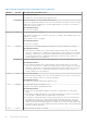
Table Of Contents
- Dell EMC PowerVault ME4 Series Storage System Owner’s Manual
- Contents
- Storage system hardware
- Troubleshooting and problem solving
- Module removal and replacement
- ESD precautions
- Dealing with hardware faults
- Firmware updates
- Continuous operation during replacement
- Shutting down attached hosts
- Shutting down a controller module
- Verifying component failure
- Customer-replaceable units (CRUs)
- Attach or remove the front bezel of a 2U enclosure
- Replacing a drive carrier module in a 2U enclosure
- Replacing a DDIC in a 5U enclosure
- Replacing a controller module or IOM in a 2U or 5U enclosure
- Replacing a power supply unit (PSU) in a 5U enclosure
- Replacing a fan cooling module (FCM) in a 5U enclosure
- Replacing a power cooling module (PCM) in a 2U enclosure
- Completing the component installation process
- Verifying component operation
- Performing updates in PowerVault Manager after replacing an FC or SAS HBA
- Events and event messages
- Connecting to the CLI port using a serial cable
- Technical specifications
- Standards and regulations

9. If replacing two PCMs, repeat steps 5 through 8.
Installing a PCM
Refer to Removing a PCM (1 of 2) on page 70 and Removing a PCM (2 of 2) on page 70 when performing this procedure, but
ignore the directional arrows—since you will insert the module into the slot rather than extract.
NOTE: Handle the PCM carefully, and avoid damaging the connector pins. Do not install the PCM if any pins appear to be
bent.
1. Check for damage, especially to all module connectors.
2. With the PCM handle in the open position, slide the module into the enclosure, taking care to support the base and weight of
the module with both hands.
3. Cam the module home by manually closing the PCM handle. You should hear a click as the latch handle engages and secures
the PCM to its connector on the back of the midplane.
4. Connect the power cable to the power source and the PCM.
5. Secure the strain relief bales.
6. Using the management interfaces (the PowerVault Manager or CLI), verify whether the health of the new PCM is OK. Verify
that the green PCM OK LED is on/blinking per PCM LED states on page 33. Verify that cooling fans are spinning with no fail
states. Verify that Ops panel states show no amber module faults.
7. If replacing two PCMs, repeat steps 1 through 5.
Completing the component installation process
This section provides a procedure for ensuring that the components installed in the replacement controller enclosure chassis
function properly.
1. Reconnect data cables between devices, as needed, to return to the original cabling configuration:
● Between cascaded storage enclosures.
● Between the controller and peripheral or SAN devices.
● Between the controller enclosure and the host.
2. Reconnect power cables to the storage enclosures.
Verifying component operation
1. Restart system devices by moving the power switch on the power supply to the On position in the following sequence:
a. Expansion enclosures first.
b. Controller enclosure next.
c. Data host last (if powered down for maintenance purposes).
Allow time for each device to complete its Power On Self Tests (POST) before proceeding.
2. If you are unable to connect the storage system, ping the management IP addresses for both controller modules. If the
pings fail, check if the management IP addresses are set on the controller modules. If the IP address are not set, enter the
management IP address of both controller modules.
3. If the controller modules contain iSCSI ports, ping the IP address of the iSCSI ports. If the pings fail, check if IP addresses
are set on the iSCSI ports of the controller modules. If the IP address are not set, enter the IP address of the iSCSI ports on
both controller modules.
4. Perform a rescan to force a fresh discovery of all expansion enclosures connected to the controller enclosure. This step
clears the internal SAS layout information, reassigns enclosure IDs, and ensures the enclosures are displayed in the proper
order. Use the CLI or PowerVault Manager to perform the rescan:
To perform a rescan using the CLI, enter the following command: rescan
To perform a rescan using the PowerVault Manager:
a. Verify that both controllers are operating normally.
b. In the System topic, select Action > Rescan Disk Channels.
c. Select Rescan.
Module removal and replacement
71