Dell EMC Edge 510 LTE Installation guide October 2020 Rev.
Notes, cautions, and warnings NOTE: A NOTE indicates important information that helps you make better use of your product. CAUTION: A CAUTION indicates either potential damage to hardware or loss of data and tells you how to avoid the problem. WARNING: A WARNING indicates a potential for property damage, personal injury, or death. © 2016 - 2020 Dell Inc. or its subsidiaries. All rights reserved. Dell, EMC, and other trademarks are trademarks of Dell Inc. or its subsidiaries.
Contents Chapter 1: About this guide........................................................................................................... 4 Related documents..............................................................................................................................................................4 Information symbols............................................................................................................................................................
1 About this guide This guide provides site preparation recommendations, step-by-step procedures for installing your device, and connecting to a power source. CAUTION: To avoid electrostatic discharge (ESD) damage, wear grounding wrist straps when handling this equipment. NOTE: Only trained and qualified personnel can install this equipment. Read this guide before you install and power up this equipment. This equipment contains two power cables. Disconnect both power cables before servicing.
CAUTION: The Caution icon signals information about situations that could result in equipment damage or loss of data. NOTE: The Warning icon signals information about hardware handling that could result in injury. NOTE: The ESD Warning icon requires that you take electrostatic precautions when handling the device.
2 Edge 510 LTE The Dell EMC Edge 510 LTE simplifies SD-WAN integration into your IT solution. It connects the service provider edge or smallto-medium branch locations to the cloud. The Edge 510 LTE comes with VeloCloud software preinstalled. ● Dell EMC SD-WAN Edge—a hardware device with VeloCloud/VMware software preinstalled. ● VeloCloud/VMware Gateway—a virtual machine that is hosted on the Internet with the VeloCloud/VMware software preinstalled. VeloCloud/VMware manages the Gateway.
1. Power connection 12 v DC 3. Four-gigabit Ethernet connections, GE1/GE2/GE3/GE4 5. SIM card slot 2. Reset button 4. GPS antenna connector 6. Mini-USB console port Features Hardware description ● ● ● ● ● ● ● ● ● ● Edge 510—two-core CPU Four 1 GbE networking ports One dedicated Mini-USB 2.0 console port for out-of-band management Two USB 2.0 Type A ports on each side of the platform DDR3 with ECC 4 GB memory onboard.
As the system functions are in process, the service indicator displays: ● White—initial power-on and boot is in progress. ● Flashing blue—system reset or software update is in progress. ● Flashing white—VeloCloud Orchestrator function in progress. The Edge 510 LTE also includes RJ45 port status LED displays on the back of the platform. The RJ45 port status LEDs are located to the left and right of each port. Table 1.
3 Site preparations The Edge 510 LTE platform connects the service provider edge or small-to-medium branch locations. Use the platform on a desktop or optionally install the platform in a wall or rack. NOTE: If you optionally install the platform into a rack or cabinet, install the platform first, and then install any additional components such as cables or optics.
Fans and airflow The Edge510 LTE enclosure is fanless. Power connection The platform uses an AC-DC power supply. NOTE: AC power cable can not be directly connected to the platform. 1. Connect the DC power connector of the PSU into the power connector. 2. Secure by turning the lock-screw on the DC power plug. 3. Plug the AC power cable into the PSU. 4. Connect the other end of the AC power cable into an AC power outlet to power the platform.
4 Edge 510 LTE installation To install the Edge 510 LTE platform, complete the installation procedures in the order that is in this chapter. Always handle the platform and components with care. NOTE: For thermal considerations, do not stack the Edge 510 LTE platforms on top of each other. NOTE: If components are mishandled, ESD damage can occur. Always wear an ESD-preventive wrist or heel ground strap when handling the platform and components.
NOTE: Must insert SIM card with the contacts facing up until it clicks into place. Figure 2. Insert SIM card NOTE: See Configure Edge activation to enable SIM card. Desktop mount The Edge 510 LTE includes four rubber pads that provide secure and stable placement of the platform on a clean, flat surface. NOTE: Ensure that the platform is in a well-ventilated environment with clearance around the air vents. Wall mount The Edge 510 LTE includes two wall mount brackets.
NOTE: The rubber feet must be removed because they share the same screw holes with the wall mount brackets. 2. Using a torque screwdriver, attach the included wall mount brackets to the platform using the four M3 screws that mounted the rubber feet. 3. Anchor the screws into the wall surface. 4. Slide the cross-shaped cutouts of the wall.
WARNING: When mounting the platform to the wall, face the Ethernet ports up towards the ceiling and the system status LED panel down, facing the floor. Keyhole-shaped bracket installation Rack mount As an option, you can mount the Edge 510 LTE platform to a dual rackmount tray. Purchase the dual rackmount tray separately. You must have a torque screwdriver to complete this installation. NOTE: Verify that you torque to 5 lb-in when driving the screws into the bracket and platform.
2. Use the eight included M3 screws to attach the platforms to the dual rackmount tray. Use four screws for each platform. 3. Install the rackmount tray in to your rack using the installation instructions included with the tray. Platform power-on Before you turn on the platform, reinspect the rack mounting or desktop placement of the platform. Verify that the power supply to the Edge 510 LTE is secure.
Install the device in an area that meets the following safety requirements: ● ● ● ● Place unit near a properly grounded AC power outlet. In a temperature-controlled room with a temperature range from 0°C to 40°C (32°F to 104°F). In a dry, clean, and well-ventilated room away from heat sources such as hot air vents or direct sunlight Away from severe electromagnetic noise The numbers one through four in the following figure correspond to the setup procedure: 1.
NOTE: By default, the Edge gets a DHCP IP address from the ISP on the WAN uplink. When the WAN connection is fully operational, the service indicator LED on the front of the Edge is green. 3. Connect local devices such as computers and switches ONLY to the GE1 or GE2 ports, or through the Edge WiFi. NOTE: Use ONLY GE1 or GE2 1 Gb Ethernet ports for LAN connection to a laptop or switch.
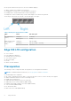
6. Click the activation url which updates the cellular area and activates the SIM card in the Edge unit. Configure Edge activation NOTE: The following activation is through the WAN ports (GE3 or GE4) NOT through a carrier SIM card. NOTE: For SIM card activation, contact your IT department. Contact Dell for a Velocloud Orchestrator (VCO) account. Use you personal computer to connect to your VCO account to request an activation key and configure the new Edge unit. Assign an activation key.
Enter a valid email address in the activation popup window that is sent to a site contact. Sample instructions that are provided in the activation email message body to a Site Contact to connect and activate Edge hardware. Add additional instructions for connecting specific site WAN and LAN networks to Edge. NOTE: If an Edge 510 LTE device configured for release 3.4, the Activation email contains cellular settings (for example SIM PIN, Network, APN, Username).
5 Specifications This section lists the Edge 510 LTE Series specifications. NOTE: For RoHS information, see Restricted Material Compliance. Topics: • • • • Chassis physical design IEEE standards Agency compliance Product recycling and disposal Chassis physical design Table 2. Edge 510 LTE specifications Feature Specification Size ● 8.1 in x 7.1 in x 1.57 in (W x D x H) ● 20.6 cm x 18.0 cm x 4.0 cm (W x D x H) Weight NOTE: Platform weight does not include power adapter weight. ● 2.29 lbs ● 0.
IEEE standards The Edge 510 LTE complies with the following IEEE standards: ● 802.1ab—LLDP ● 802.1ax—Layer 2 ● 802.1d, 802.1w, 802.1s, 802.1x—Mgmt/Security; 802.3x—Layer 2 Agency compliance The Edge 510 LTE complies with the following safety and agency requirements: USA Federal Communications Commission statement CAUTION: The use of external signal amplifiers in-line with the transceiver antennas is strictly prohibited. CAUTION: Use only the antenna(s) which have been approved by the applicant.
CAUTION: Use only the antenna(s) which have been approved by the applicant. Non-approved antenna(s) may produce unwanted spurious or excessive RF transmitting power which may lead to a violation of FCC/IC limits and is prohibited. CAUTION: L'utilisation d'amplificateurs de signal externes en ligne avec les antennes de l'émetteur-récepteur est strictement interdite. CAUTION: Utilisez uniquement les antennes approuvées par le demandeur.
Brasil – Aviso da Anatel Este equipamento opera em caráter secundário, isto é, não tem direito a proteção contra interferência prejudicial, mesmo de estações do mesmo tipo, e não pode causar interferência a sistemas operando em caráter primário. European Union EU Declaration of Conformity Declaration #550004 for Velocloud Edge Wireless Gateway Model: Edge510 Manufactured by: Velocloud Networks, Inc.
Taiwan Taiwanese certification of compliance 台灣: 國家通訊傳播委員會 低功率電波輻射性電機管理辦法 第十二條經型式認證合格之低功率射頻電機,非經許可,公司、商 號或使 用者均不得擅自變更頻率、加大功率或變更原設計之特性及功能。 第十四條低功率射頻電機之使用不得影響飛航安全及 干擾合法通信;經發 現有干擾現象時,應立即停用,並改善至無干擾時方得繼續使用。 前項合法通信,指依電信法規定作業之 無線電通信。低功率射頻電機須忍受合法通信或工業、科學及醫療用電波輻射性電機設備之干擾。 在 5.25-5.35 秭赫頻帶內操 作之無線資訊傳輸設備,限於室內使用 Product recycling and disposal Recycle or discard this appliance according to applicable local and national regulations.
6 Dell EMC support The Dell EMC support site provides documents and tools to help you effectively use Dell EMC equipment and mitigate network outages. Through the support site you can obtain technical information, access software upgrades and patches, download available management software, and manage your open cases. The Dell EMC support site provides integrated, secure access to these services. To access the Dell EMC support site, go to www.dell.com/support/.