
Owners Manual


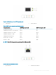


Item Indicator, button, or connector Icon Description
4 sled release lock N/A
Enables you to remove the sled from the enclosure.
5 rear power button N/A
Enables you to power on the sled while accessing it from the
rear.
6 iDRAC or NIC port Enables you to remotely access iDRAC. For more information,
see the iDRAC User’s Guide at Dell.com/poweredgemanuals.
7 mini display port Enables you to connect a display device to the system. For more
information, see Technical specications.
8 iDRAC Direct micro USB port
Enables you to connect a portable device to the sled.
9 OCP card slot N/A Enables you to connect Open Compute Project (OCP)
expansion cards. For more information, see Technical
specications.
10 EST pull out tab N/A This tab has the unique Express Service Code, Service Tag, and
MAC address labels.
11 system id indicator The System Identication (ID) LED is available on the back of
the system. Press the system ID button on the front of the
enclosure to identify a system in a rack.
12 USB 3.0 port (2)
The USB ports are 9-pin and 3.0-compliant. These ports enable
you to connect USB devices to the system.
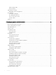
Network ports indicator codes
Figure 2. LAN indicators on the QSFP carrier card
1
Link indicator
8 XC6420 Series XC Core System overview