
Setup Guide
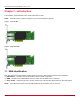
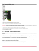

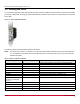
Table Of Contents

Broadcom LPe-HBA-IG128-100-2CS
10
Emulex Fibre Channel Host Bus Adapters Installation Guide
2.5 Viewing the LEDs
You can view the green and yellow LEDs through openings in a stand-up HBA's mounting bracket. The yellow LED indicates
port activity or link speed, and the green LED indicates firmware operation. Each port has a corresponding set of yellow and
green LEDs.
Figure 10: Optical HBA LED Indicators
The following table summarizes POST conditions and results:
NOTE: For the link rate conditions, a 1s pause occurs when the yellow LED is off between each group of fast blinks (2, 3,
4, or 5, depending on the HBA). Observe the LED sequence for several seconds to be sure you have correctly
identified the pattern.
Table 1: POST Conditions and Results
Yellow LED Green LED State
Off Off No SFP module installed or a boot failure occurred (dead board)
On Off POST failure (dead board)
Slow blink Off Boot failure after POST
Flashing Off POST processing in progress
Off On Failure in the common code module
On On Failure in the common code module
1 fast blink On Normal (link up at 2GFC) (legacy compatibility only)
2 fast blinks On Normal (link up at 4GFC)
3 fast blinks
4 fast blinks (LPe12002-M8
HBAs only)
On Normal (link up at 8GFC)
4 fast blinks On Normal (link up at 16GFC)
5 fast blinks On Normal (link up at 32GFC)
Off Slow blink Normal (link down)
Fast blink Fast blink Beaconing