
Users Guide
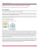
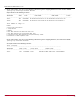
Table Of Contents
- Table of Contents
- Chapter 1: Introduction
- Chapter 2: Installation
- Chapter 3: Configuration
- 3.1 ESXi Command Line Tool Transition
- 3.2 FC Driver Configuration
- 3.2.1 Configuration Methods for FC Driver Parameters
- 3.2.2 Emulex ExpressLane Support
- 3.2.3 FC-SP-2 Authentication (DH-CHAP) Support
- 3.2.4 Trunking Support
- 3.2.5 Dynamically Adding LUNs
- 3.2.6 Dynamically Adding Targets
- 3.2.7 FC Driver Module Parameters
- 3.2.8 Creating an FC Remote Boot Disk
- 3.2.9 Managing Devices through the CIM Interface
- 3.2.10 Installing the Emulex CIM Provider
- 3.2.11 Creating, Deleting, and Displaying vPorts
- 3.2.12 Configuring VVols
- 3.2.13 Adjusting the LUN Queue Depth
- 3.3 Configuring NVMe over FC on a NetApp Target
- 3.4 Configuring NVMe over FC on an Initiator System
- Chapter 4: Troubleshooting the FC Driver
- Chapter 5: Troubleshooting the NVMe Driver
- Appendix A: esxcli Management Tool
- Appendix B: lpfc Driver BlockGuard Functionality
- Appendix C: Using the VMID Feature on a Brocade Switch
- Appendix D: Using the VMID Feature on a Cisco Switch
- Appendix E: NPIV Configuration
- Appendix F: License Notices

Broadcom DRVVM-UG128-100
103
Emulex Drivers for VMware ESXi User Guide
Appendix B: lpfc Driver BlockGuard Functionality
This appendix describes how to enable BlockGuard and set lpfc driver module parameters.
B.1 Overview
The BlockGuard feature checks the integrity of data read and written between the host and the disk through the SAN. This
check is implemented through the DIF defined in the ANSI T10 standard.
The Emulex lpfc driver supports T10 DIF Type 1. In the Type 1 implementation, the 8-byte DIF consists of a Ref tag (or
LBA), an App tag, and a Guard tag (or CRC). A Type 1 DIF is defined as having a 2-byte Guard tag, a 2-byte App tag, and a
4-byte Ref tag, which consist of the lower 32 bits of the LBA.
The following figure shows a data block (with a 512-byte sector) with the 8-byte footer attached to the end. The contents of
the 8-byte footer are shown with the fields that make up the Type 1 DIF; the Guard tag, the App tag, and the Ref tag. The
App tag is not used by the lpfc driver.
Figure 1: Data Block Showing Type 1 DIF
When data is written, the DIF is generated by the host, or by the adapter, based on the block data and the LBA. The DIF
field is added to the end of each data block, and the data is sent through the SAN to the storage target. The storage target
validates the CRC and Ref tag and, if correct, stores both the data block and DIF on the physical media. If the CRC does
not match the data, the data was corrupted during the write. A Check Condition is returned to the host with the appropriate
error code. The host records the error and retransmits the data to the target. In this way, data corruption is detected
immediately on a write and is never committed to the physical media. On a read, the DIF is returned along with the data
block to the host, which validates the CRC and Ref tags. Because this validation is done by the hardware, it adds a very
small amount of latency to the I/O.
The format of the Guard tag can optionally be an IP checksum instead of the CRC mandated by the T10 DIF. This can be
beneficial because the initiator host uses less CPU overhead to generate an IP checksum than it does with a CRC. The IP
checksum is typically passed as the Guard tag between the initiator host and the adapter. The adapter hardware will translate
the IP checksum into a CRC, or vice versa, on data being sent to or received from the wire. The CRC is called a DIF
protection type, and the IP checksum is referred to as a DIX protection type.