
Users Guide
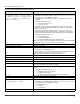

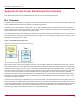
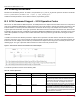
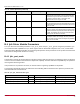
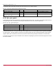

Table Of Contents
- Table of Contents
- Chapter 1: Introduction
- Chapter 2: Installation
- Chapter 3: Configuration
- 3.1 ESXi Command Line Tool Transition
- 3.2 FC Driver Configuration
- 3.2.1 Configuration Methods for FC Driver Parameters
- 3.2.2 Emulex ExpressLane Support
- 3.2.3 FC-SP-2 Authentication (DH-CHAP) Support
- 3.2.4 Trunking Support
- 3.2.5 Dynamically Adding LUNs
- 3.2.6 Dynamically Adding Targets
- 3.2.7 FC Driver Module Parameters
- 3.2.8 Creating an FC Remote Boot Disk
- 3.2.9 Managing Devices through the CIM Interface
- 3.2.10 Installing the Emulex CIM Provider
- 3.2.11 Creating, Deleting, and Displaying vPorts
- 3.2.12 Configuring VVols
- 3.2.13 Adjusting the LUN Queue Depth
- 3.3 Configuring NVMe over FC on a NetApp Target
- 3.4 Configuring NVMe over FC on an Initiator System
- Chapter 4: Troubleshooting the FC Driver
- Chapter 5: Troubleshooting the NVMe Driver
- Appendix A: esxcli Management Tool
- Appendix B: lpfc Driver BlockGuard Functionality
- Appendix C: Using the VMID Feature on a Brocade Switch
- Appendix D: Using the VMID Feature on a Cisco Switch
- Appendix E: NPIV Configuration
- Appendix F: License Notices

Broadcom DRVVM-UG128-100
105
Emulex Drivers for VMware ESXi User Guide
B.4 lpfc Driver Module Parameters
The lpfc driver has two module parameters: lpfc_prot_mask and lpfc_prot_guard. Using these parameters, you
can control which DIF capabilities the lpfc driver registers with the ESXi SCSI subsystem. This, in turn, controls which
initiator operations (BlockGuard profiles) are used during I/O operations. These parameters are set up when the driver loads
and cannot be changed while the driver is running.
B.4.1 lpfc_prot_mask
This parameter controls the DIF operations that the driver registers with the hypervisor. The hypervisor selects an operation
to use for each I/O command that matches the adapter DIF capability. The driver indicates its capabilities by the operations
that it registers with the hypervisor.
If the parameter is not passed to the driver, the default results in registering capabilities for all profiles.
The SCSI layer will typically use the bit masks listed in the following table to determine how to place the protection data
associated with I/Os to the SCSI host.
READ_STRIP Unprotected Protected Reads the data and protection data from the target. The
adapter verifies data integrity, discards protection data,
and transfers only the data to the initiator host. It does
not send the protection data to the initiator host.
Protection data is sent only on the SAN.
WRITE_INSERT Unprotected Protected Transfers the data from the initiator host. The adapter
then generates protection data and writes both the data
and protection data to the target. Protection data is sent
only on the SAN.
WRITE_PASS Protected Protected Transfers the data and protection data from the initiator
host to the adapter. The adapter verifies protection data
and writes both data and protection data to the target on
the SAN. The adapter can convert the protection data
Guard tag from IP checksum to CRC.
WRITE_STRIP Protected Unprotected Transfers data and protection data from the initiator host.
The adapter verifies data integrity, discards protection
data, and writes only the data to the target. No protection
data is sent on the SAN.
Table 13: lpfc_prot_mask Protection Types
Flag Value Indicates Description
VMK_SCSI_TYPE1_PROT 1 Adapter supports T10 DIF Type 1 Adapter-to-target Type 1 protection
VMK_SCSI_DIX_TYPE0_PROT 8 Adapter supports DIX Type 0 Host-to-adapter protection only
VMK_SCSI_DIX_TYPE1_PROT 16 Adapter supports DIX Type 1 Host-to-adapter Type 1 protection
Table 12: Initiator Operations (Continued)
Initiator Operation Initiator Host <-> Adapter Adapter <-> Target Comment