
Install Guide


Installation and Setup Guide
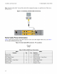
3 Connecting the Array Cables
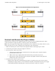
– Each UPS (not included) should be on a different circuit and must provide the correct type of voltage for
an adequate amount of time.
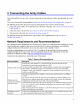
– Alternately, connect one power supply and cooling module to a UPS system and connect the other mod-
ule to a different source of power.
Caution: Do not turn on power to the array yet.
Figure 6: Connecting the Power Cables
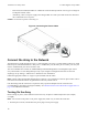
Connect the Array to the Network
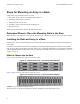
The PS4110 array model includes two Type 17 control modules. The Type 17 control module contains two 10Gb
Ethernet ports, both labeled Ethernet 0. One port is a 10GBASE-T port, the other port is an SFP+ port. Only one
of these 10Gb Ethernet ports can be used at a time.
The control modules also include one 10Mb/100Mb port labeled Management. The management port cannot
carry iSCSI traffic. Use the management port only if you configure a management network. See the Dell
EqualLogic Group Manager Administrator's Manual for more information.
Obtain the appropriate number of copper or optical 10GbE network cables.
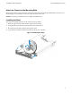
Note: Optical cables transmit data through pulses of light. It is very important to route all optical cables with no
more than a 4-inch bend radius at any point between the array and the switch.
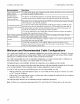
One functioning network connection is required for array operation. Multiple network connections are
recommended for performance and high availability. See Minimum and Recommended Cable Configurations on
page 10 for additional information.
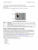
Turning On the Array
Before turning on power, allow sufficient time for the array to adjust to ambient temperature (for example,
overnight).
Note: You can turn on the power to one power supply first (either one), or both at the same time.
1. Find the power switch, located below the power plug on each power supply.
12