
Owners Manual


硬件用户手册 1 基本存储阵列信息
注 : LED 指示灯作为不可热交换的内置机箱控制面板的一部分,必须由技术支持人员进行更换。
在阵列加电顺序过程中,这些 LED 指示灯会在不同状态间循环变换,直到阵列完全启动且当前控
制模块已经确定。
背面板特征和指示灯
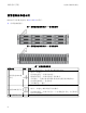
PS4110 的背面如图 5 中所示。
表 2 介绍背面板特征。
图 5: 背部面板特征
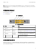
表 2: 阵列背部面板特征
项 部 件 标 识 符 说 明
1 电源开关 无
电源开关控制对阵列的供电输出。每个电源设备上
一个。
2 电源装置 (PSU)
PSU0( 左)
PSU1( 右)
阵列的电源和冷却风扇模块。
有关详细信息,请参阅
电源设备
LED
指示灯
第
33
页
上
。
3
控制模块
CM0( 顶部)
CM1( 底部)
控制模块提供:
• 阵列和使用存储的应用程序之间的数据通道
• 针对阵列的阵列管理功能
4
控制模块释放拉杆 无 用以从阵列中卸下控制模块。
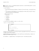
关闭 和重新启动 阵 列
PS Series 阵列包括冗余、可热交换的磁盘驱动器、电源设备以及控制模块( 在双控制模块阵列中) 。
如果有正常工作的组件可用,则可卸下冗余的组件而不会影响操作。否则,建议您在卸下组件之
前完全关闭阵列并关闭电源。
5