PS4110 Depolama Dizileri Donanım Kullanıcı El Kitabı sistem Sürüm 1.
Telif Hakkı 2011 Dell Inc. Tüm hakları saklıdır. Dell ve EqualLogic; Dell Inc. şirketinin ticari markalarıdır. Burada geçen tüm ticari markalar ve tescilli ticari markalar sahiplerinin mülkiyetindedir. Bu belgedeki bilgiler önceden bildirilmeksizin değiştirilebilir. Dell'in yazılı izni olmadan herhangi bir şekilde çoğaltılması kesinlikle yasaktır.
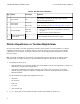
İçindekiler 1 Temel Depolama Dizisi Bilgileri Notlar, Dikkat Edilecek Noktalar ve Uyarılar Önerilen Araçlar Kasa Tipleri Dizi Özellikleri Arka Panel Özellikleri ve Göstergeleri Dizinin Kapatılması ve Yeniden Başlatılması 2 Sürücülerin Bakımının Yapılması Sürücü Türleri Hakkında Arızalı Sürücülerin Belirlenmesi Sürücü LED'lerinin Yorumlanması Bir Sürücüsü Arızalandığında Dizinin Davranışı Sürücü Kullanım Gereksinimleri Sürücü Kurulum Yönergeleri ve Kısıtlamaları 3 Kontrol Modüllerinin Bakımının Yapılması K
1 Temel Depolama Dizisi Bilgileri Bu bölüm, bir depolama dizisinde değiştirilebilir bileşenlerin konumu ve basit işlemleri, ihtiyacınız olan araçlar ve ekipmanlar, donanımın elektrostatik boşalmadan korunması ve gücün açıp kapatılması işlemleri hakkında bilgi içerir. Notlar, Dikkat Edilecek Noktalar ve Uyarılar NOT, sisteminizden daha iyi şekilde yararlanmanıza yardımcı olacak önemli bilgiler verir. DİKKAT, yönergelere uyulmadığında donanımın zarar görebileceğini veya veri kaybı olabileceğini belirtir.
Donanım Kullanıcı El Kitabı sistem 1 Temel Depolama Dizisi Bilgileri Donanımı Koruma PS Serisi diziyi elektrostatik boşalmadan koruyun. Dizi donanımıyla işlem yaparken, elektrostatik bileklik veya benzer bir koruma yöntemi kullandığınızdan emin olun. Bileklik kullanmak için: 1. Sargılı kabloda bulunan çelik kopçayı esnek banttaki çiviye takın. Bkz. Şekil 1. Şekil 1: Elektrostatik Bilekliği Kullanma 2. Bandı bileğinize yakın şekilde takın. 3. Bandı toprağa bağlayın.
Donanım Kullanıcı El Kitabı sistem 1 Temel Depolama Dizisi Bilgileri Çerçeve Çerçeve dizinin fiziksel güvenliğini sağlamak için dizinin önüne monte edilen isteğe bağlı bir trim panelidir. Sürücüye erişmek ve bakımını yapmak için çerçeveyi çıkarmanız gerekir. Çerçeve model numarasını gösteren bir etikete sahiptir. Çerçeveyi Çıkarma Çerçeveyi çıkarma adımları tüm dizi modelleri için aynıdır. 1. Çerçeve anahtarını kullanarak çerçevenin kilidini açın. 2.
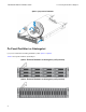
Donanım Kullanıcı El Kitabı sistem 1 Temel Depolama Dizisi Bilgileri Şekil 2: Çerçevenin Takılması Ön Panel Özellikleri ve Göstergeleri Çerçevesiz olarak PS4110 önden görünümü için bkz. Şekil 3 ve Şekil 4. Tablo 1'de ön panel özellikleri açıklanmıştır.
Donanım Kullanıcı El Kitabı sistem 1 Temel Depolama Dizisi Bilgileri Tablo 1: Ön Panel Özellik Tanımları Öğe Gösterge 1 Dizi durumu LED'i 2 Güç LED'i 3 Sürücü Serbest Bırakma Mandalı Simge Açıklama Dizi durum LED'i dizi gücü açıkken yanar. • Off—Güç yok. • Sabit mavi—Dizi durumu düzgün. • Yavaş yanıp sönen mavi—Dizi durumu Standby (Bekleme) modunda. • Yanıp sönen mavi—Diziyi belirlemek için yönetici isteği (Grup Yöneticisi çevrimiçi yardıma bakın). • Sabit sarı—Kritik durum.
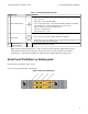
Donanım Kullanıcı El Kitabı sistem 1 Temel Depolama Dizisi Bilgileri Tablo 2: Dizi Arka Panel Özellikleri Öğe Özellik Tanımlayıcı Açıklama 1 Güç anahtarı Yok Güç anahtarı, dizideki güç kaynağı çıkışını denetler. Her güç kaynağında bir tane. 2 Güç kaynağı birimi (PSU) PSU0 (sol) Dizi için güç kaynağı ve soğutma fanı modülü. PSU1 (sağ) 3 Kontrol Modülü Daha fazla bilgi için bkz. Güç Kaynağı LED'leri sayfa 38.
Donanım Kullanıcı El Kitabı sistem 1 Temel Depolama Dizisi Bilgileri 3. Bir sonraki adımda gösterildiği gibi shutdown komutunu girin. login: grpadmin Password: Welcome to Group Manager Copyright 2001-2011 Dell Inc. group1> shutdown Diziyi kapatmak için seri bir bağlantı kullanıyorsanız, "press any key" (herhangi bir tuşa basın) mesajı görüntülendiğinde gücü kapatmak emniyetlidir. (Herhangi bir tuşa basılması her iki kontrol modülünü de yeniden başlatır.
2 Sürücülerin Bakımının Yapılması Arızalanmış bir sürücüyü dizi çalışır durumdayken değiştirebilirsiniz. Sürücü Türleri Hakkında Yapılandırmanıza bağlı olarak, diziniz dahili sürücü yuvaları içinde en fazla 24 adet 2,5 inç SAS sürücüyü veya en fazla 12 adet 3,5 inç SAS sürücüyü destekler. Sürücüler arka panele sürücü taşıyıcıları ile bağlıdır ve çalışırken takılabilirler. Sürücüler, belli dizilere uyması için ve diğer DELL dizilerine ya da DELL Inc.
Donanım Kullanıcı El Kitabı sistem 2 Sürücülerin Bakımının Yapılması Sürücü LED'lerinin Yorumlanması 3,5 inç sürücü üzerindeki LED'ler Şekil 6'da görülmektedir. 2,5 inç sürücü üzerindeki LED'ler Şekil 7'de görülmektedir. Sürücü LED durumları Tablo 4'te açıklanmıştır.
Donanım Kullanıcı El Kitabı sistem 2 Sürücülerin Bakımının Yapılması Bir Sürücüsü Arızalandığında Dizinin Davranışı Dizinin bir sürücü arızasını nasıl ele alacağı, yedek sürücünün mevcut olup olmamasına ve arızalı sürücüye sahip olan RAID setinin çalışmaya devam edip edemediğine bağlıdır. Örneğin: • Yedek sürücü varsa, dizi bunu otomatik olarak arızalı sürücünün yerine kullanır. Yeniden yapılandırma tamamlandığında performans normale döner.
Donanım Kullanıcı El Kitabı sistem 2 Sürücülerin Bakımının Yapılması Sürücü Kurulum Yönergeleri ve Kısıtlamaları • En yüksek kullanılabilirliği sağlamak için arızalanan bir sürücüyü en kısa sürede değiştirin. • Dizi içerisine sadece aynı tip, hız ve dönme oranındaki sürücüleri takın. • Sürücünün dizi modeli için doğru konumda yerleştirildiğinden emin olun. Bkz. Ön Panel Özellikleri ve Göstergeleri sayfa 4. • Aynı dizide farklı kapasitelerde sürücüler kullanabilirsiniz.
Donanım Kullanıcı El Kitabı sistem 2 Sürücülerin Bakımının Yapılması Şekil 8: 2,5 İnç Sürücünün Çıkarılması 13
Donanım Kullanıcı El Kitabı sistem 2 Sürücülerin Bakımının Yapılması 2,5 İnç Sürücünün Takılması 2,5 inç sürücüler, sürücü serbest bırakma mandalı üstte ve sürücü etiketi aşağıda olacak şekilde dikey olarak takılırlar. 1. Sürücü üzerinde işlem yaparken elektrostatik bileklik takın. Donanımı Koruma sayfa 2. 2. Sürücü serbest bırakma mandalını açın. 3. Sürücüyü taşıyıcıyla tutun ve sürücüyü yuvadan içeriye itin (Şekil 9'daki belirtme çizgisi 1). 4. Sürücüyü tamamen yuvaya itin (belirtme çizgisi 2).
Donanım Kullanıcı El Kitabı sistem 2 Sürücülerin Bakımının Yapılması Şekil 9: 2,5 İnç Sürücünün Takılması Ön paneldeki LED'leri, Sürücü LED'lerinin Yorumlanması sayfa 10'de açıklandığı şekilde inceleyerek, sürücünün çalıştığını doğrulayın. Ayrıca, GUI Member Disks (GUI Üye Diskler) penceresi ve CLI member select show disks komutu çıktısını inceleyin.
Donanım Kullanıcı El Kitabı sistem 2 Sürücülerin Bakımının Yapılması 3,5 İnç Sürücünün Çıkarılması 1. Çerçeveyi çıkarın. Bkz. Çerçeveyi Çıkarma sayfa 3. 2. Serbest bırakma düğmesine basın (Şekil 10'deki belirtme çizgisi 1). Sürücü mandalı açılır ve sürücü diziden yarıya kadar çıkar (belirtme çizgisi 2). 3. Sürücüyü kolla sürücü yuvasından tamamen çıkana kadar çekin (belirtme çizgisi 3).
Donanım Kullanıcı El Kitabı sistem 2 Sürücülerin Bakımının Yapılması 3,5 İnç Sürücünün Takılması 3,5 inç sürücüler sürücü serbest bırakma mandalı sola ve sürücü etiketi sağa gelecek şekilde yatay yerleştirilirler. 1. Sürücü üzerinde işlem yaparken elektrostatik bileklik takın. Donanımı Koruma sayfa 2 2. Sürücü serbest bırakma mandalını açın. 3. Sürücüyü taşıyıcıyla tutun ve sürücüyü yuvadan içeriye itin (Şekil 11'deki belirtme çizgisi 1). 4. Sürücüyü tamamen yuvaya itin (belirtme çizgisi 2).
Donanım Kullanıcı El Kitabı sistem 2 Sürücülerin Bakımının Yapılması Şekil 11: 3,5 İnç Sürücünün Takılması Ön paneldeki LED'leri, Sürücü LED'lerinin Yorumlanması sayfa 10'da açıklandığı şekilde inceleyerek, sürücünün çalıştığını doğrulayın. Ayrıca, GUI Member Disks (GUI Üye Diskler) penceresi ve CLI member select show disks komutu çıktısını inceleyin.
Donanım Kullanıcı El Kitabı sistem 2 Sürücülerin Bakımının Yapılması Boş Sürücüyü Çıkarma Uyari: Uygun sistem soğutması için tüm boş sürücü bölmesi kapaklarının takılı olması gerekir. 1. Çerçeveyi çıkarın. Bkz. Çerçeveyi Çıkarma sayfa 3. 2. Serbest bırakma sekmesine basın ve boş sürücüyü sürücü yuvasından çıkana kadar dışarı doğru kaydırın. Bkz. Şekil 12 veya Şekil 13.
Donanım Kullanıcı El Kitabı sistem Boş Sürücüyü Takma 1. Çerçeveyi çıkarın. Bkz. Çerçeveyi Çıkarma sayfa 3. 2. Sürücü kapağını yerine oturana kadar sürücü yuvasına yerleştirin. 3. Çerçeveyi takın.
3 Kontrol Modüllerinin Bakımının Yapılması Farklı PS Series dizi modelleri farklı kontrol modülü tipleri içerir. Kasa türü, kontrol modülü çifti ve sürücülerin bileşimi PS Series dizi modeli numarasını belirler. PS Series dizisindeki kontrol modülleri Grup Yöneticisi GUI, komut satırı referansı ve tüm dizi ve depolama yönetimi fonksiyonlarını ve özelliklerini gösteren PS Series ürün bilgisini içerir.
Donanım Kullanıcı El Kitabı sistem • 3 Kontrol Modüllerinin Bakımının Yapılması Kontrol modülünü yeniden yerleştirmek için diziden ayırmaya yarayan bir serbest bırakma düğmesi ve mandal. Serbest bırakma kolu, etkinliği algılayan ve veriyi korumak amacıyla dizinin veriyi geçici olmayan depoya kaydetmesini sağlayan bir anahtara sahiptir. Dikkat: Dizideki kontrol modülü tiplerini karıştırmayın. Daima her iki kontrol modülünün de aynı tip ve renkte olduğundan emin olun.
Donanım Kullanıcı El Kitabı sistem 3 Kontrol Modüllerinin Bakımının Yapılması Şekil 14: Dikey Yük Devretmeyi Desteklemek İçin Önerilen Ağ Yapılandırması Not: Ethernet bağlantı noktası herhangi bir kontrol modülü üzerinde yük devretmek için hazır bulunuyorsa ama kullanımda değilse LED'leri yanmayacaktır.
Donanım Kullanıcı El Kitabı sistem 3 Kontrol Modüllerinin Bakımının Yapılması Tablo 5: Ethernet ve Yönetim Bağlantı Noktası LED Açıklamaları 10GBASE-T Ethernet LED Konumu Durum Açıklama Off (Kapalı) Güç yok, ağa bağlı değil veya pasif. On (Açık) Ağa bağlı. Off (Kapalı) Güç yok, gönderme yok veya alma yok. On (Açık) Gönderiyor veya alıyor. Sol (Bağlantı) Sağ (İşlem) SPF+ Ethernet LED Konumu Durum Açıklama Off (Kapalı) Güç yok, ağa bağlı değil veya pasif. On (Açık) Ağa bağlı.
Donanım Kullanıcı El Kitabı sistem • 3 Kontrol Modüllerinin Bakımının Yapılması Group Manager (Grup Yöneticisi) GUI ve CLI çıktısı. Üye Denetleyicileri penceresi veya member select show controllers komutu çıktısı not installed kontrol modülü durumunu gösterir. Dizinin arkasından bakıldığında, CM0 üstte, CM1 de alttadır. Bkz. Ön Panel Özellikleri ve Göstergeleri sayfa 4. Kontrol modülü arızalanırsa, değiştirilmesi için PS Series destek sağlayıcınızla temasa geçin.
Donanım Kullanıcı El Kitabı sistem 3 Kontrol Modüllerinin Bakımının Yapılması Kontrol Modülü Ürün Bilgisinin İdamesi Bir kontrol modülü, dizi ürün bilgisini çalıştıran bir mikro SD kartına sahiptir. Yeni ürün özellikleri ve iyileştirmelerinden faydalanmak için en son ürün bilgisi sürümünü kullanmalısınız. Dikkat: Çift kontrol modüllü bir dizide, her iki kontrol modülü aynı ürün bilgisi sürümünü kullanmalıdır aksi takdirde sadece bir kontrol modülü işlevsel olacaktır.
Donanım Kullanıcı El Kitabı sistem 3 Kontrol Modüllerinin Bakımının Yapılması Standby On/Off Düğmesi Type 17 : Type 17 kontrol modülünde Standby ON/OFF olarak etiketli küçük bir girintili düğme vardır (bkz. Şekil 16). Düğme kazara etkinleştirmeleri önlemek için gömülü durumdadır. Şekil 16: Hazırda Bekleme Düğmesi Konumu Hazırda Bekleme Özelliğini Etkinleştirme Hazırda bekleme düğmesini kullanmak için bir grup yönetimi Grup Yöneticisi GUI ya da CLI'da özelliği etkinleştirmelidir.
Donanım Kullanıcı El Kitabı sistem 3 Kontrol Modüllerinin Bakımının Yapılması Önemli Konular Bu düğmeyi sadece Grup Yöneticisi GUI ya da CLI erişiminiz olmadığı durumlarda bir üyeyi hızla kapatmanız gerektiğinde kullanın. Dikkat: Hazırda bekleme modunda o üyeden alan kullanan ya da o üyeye bağlı tüm bölümler kullanılmaz hale gelir. O üye üzerindeki tüm işlemler askıya alınır, üyeden ya da üyeye hiç bir I/O etkinliği olmaz ve üyenin ürün bilgisi çalışmaz.
Donanım Kullanıcı El Kitabı sistem 3 Kontrol Modüllerinin Bakımının Yapılması Kontrol Modülü Değiştirme Yordamları Bu bölümde, PS Series dizinizdeki kontrol modüllerinin birinin veya her ikisinin çıkarılması yordamları açıklanmıştır. Aşağıdaki değiştirme senaryoları ele alınmıştır: • Bir dizideki ikincil kontrol modülünün değiştirilmesi. • Bir dizideki aktif kontrol modülünün değiştirilmesi. • Bir dizideki her iki kontrol modülünün değiştirilmesi.
Donanım Kullanıcı El Kitabı sistem 3 Kontrol Modüllerinin Bakımının Yapılması Her İki Kontrol Modülünün Değiştirilmesi Dizideki her iki kontrol modülünü değiştirmek için aşağıdaki yordamı kullanın: 1. Öncelikle ikincil kontrol modülünü değiştirin. (Bkz. İkincil Kontrol Modülünün Değiştirilmesi sayfa 29.) 2. Etkin kontrol modülünü ikincil modül yapmak için "restart" komutunu kullanın. 3. Artık ikincil olan (yeniden başlatma öncesinde etkin olan) kontrol modülünü değiştirin. (Bkz.
Donanım Kullanıcı El Kitabı sistem 3 Kontrol Modüllerinin Bakımının Yapılması Şekil 17: Kontrol Modülünün Çıkarılması (2U Dizisi) 3. Kontrol modülünü elektrostatik yükten korunan düz bir yüzey üzerine yerleştirin. Hasar görmesini engellemek için, kontrol modülünün üzerine herhangi bir şey koymayın. 4. Arızalı bir kontrol modülünü değiştiriyorsanız, arızalı kontrol modülünden mikro SD kartını çıkarın ve kartı yerine geçecek olan kontrol modülüne takın.
Donanım Kullanıcı El Kitabı sistem 3 Kontrol Modüllerinin Bakımının Yapılması Şekil 18: Kontrol Modülünün Doğru Yönlendirilmesi Kontrol modülünü takmak için: 1. Elektrostatik bileklik veya benzeri koruyucu bir cihaz takın. Donanımı Koruma sayfa 2. 2. Turuncu renkli serbest bırakma mandalını aşağı itin (belirtme çizgisi 1) ve kolu dışarı çevirin (belirtme çizgisi 2). 3. Kontrol modülünü kasanın içine doğru direnç hissedene kadar kaydırın. Şekil 19: Kontrol Modülünün Takılması (2U dizisi) 4.
Donanım Kullanıcı El Kitabı sistem 3 Kontrol Modüllerinin Bakımının Yapılması Dizide iki kontrol modülü takılı olduğu halde GUI'de (veya CLI'de) yalnızca bir tane görünüyorsa, iki kontrol modülünün önyükleme ve eşitleme yapması için yeterince zaman tanıdığınızdan (en az beş dakika) emin olun. Eşitleme tamamlandığında, seri konsolda (bağlıysa) bir ileti görüntülenir ve ikinci modüldeki ACT LED'i turuncu yanar.
Donanım Kullanıcı El Kitabı sistem 3 Kontrol Modüllerinin Bakımının Yapılması 1. Yay mekanizmasının serbest kalması için kartı yuvasına sıkıca bastırın (Şekil 20). Mikro SD kartı kısmen yuvasından dışarı çıkacaktır. Şekil 20: Mikro SD Kartının Çıkarılması 2. Kartı düzgün şekilde yuvasından dışarı doğru nazikçe çekin. 3. Mikro SD kartını elektrostatik yükten korunan düz bir yüzey üzerine yerleştirin. Mikro SD Kartının Takılması 1.
Donanım Kullanıcı El Kitabı sistem 3 Kontrol Modüllerinin Bakımının Yapılması Şekil 21: Mikro SD Kartının Takılması 3. Diziye kontrol modülünü takın. Bkz. Kontrol Modülünün Takılması sayfa 31. 4. Kontrol modülünün çalışır durumda olduğundan emin olun. Bkz. Kontrol Modülü LED'lerinin Yorumlanması sayfa 23.
Donanım Kullanıcı El Kitabı sistem 3 Kontrol Modüllerinin Bakımının Yapılması Yönetim Bağlantı Noktasının Yapılandırılması 10/100Mbps yönetim bağlantı noktasının yapılandırılması donanım adımları ve yazılım adımları içerir. Yönetim bağlantı noktası sadece grup yönetimi trafiği ile sınırlıdır; iSCSI I/O taşımaz. Not: Bu gelişmiş bir yapılandırma olarak görülür ve ortamınız bu güvenlik seviyesine ihtiyaç gerektiriyorsa yapılabilir. Donanım Adımları 1.
4 Güç Kaynağı ve Soğutma Modüllerinin Bakımının Yapılması Dizi, iki adet çalışırken değiştirilebilir güç kaynağı ve soğutma modülünü destekleyebilir. Dizi, tek modülle sadece geçici olarak çalışabilir, dizinin uzun süreli soğutulması için iki modülün de bulunması gerekir. Güç Kaynakları Hakkında PS Serisi dizi iki güç kaynağından (PSU) güç alır. Her PSU'nun 700W'lık bir güç kaynağı vardır. Her güç kaynağının iki soğutma fanı vardır.
Donanım Kullanıcı El Kitabı sistem 4 Güç Kaynağı ve Soğutma Modüllerinin Bakımının Yapılması Güç Kaynağı Arızalarını Tanımlama Bir güç kaynağı ve soğutma modülü arızasını aşağıdakilerden herhangi biri veya tamamını kullanarak belirleyebilirsiniz: • Güç kaynağındaki ve soğutma modüllerindeki LED'ler. Ayrıntılar için bkz. Güç Kaynağı LED'lerinin Yorumlanması. • Konsol üzerindeki, olay günlüğündeki ya da Grup Yöneticisi GUI Alarm panelindeki mesajlar.
Donanım Kullanıcı El Kitabı sistem 4 Güç Kaynağı ve Soğutma Modüllerinin Bakımının Yapılması Tablo 7: Güç Kaynağı LED'leri ile İlgili Açıklamalar Öğe LED Renk Durum ON—Normal çalışma. Güç kaynağı AC gücüne bağlı ve güç anahtarı açık. Güç kaynağı modülü diziye DC gücü sağlamaktadır. 1 DC güç Aşağıdakilerden herhangi biri geçerliyse OFF: Yeşil • Güç anahtarı kapalı. • Güç kaynağı AC güç kaynağına bağlanmamış.
Donanım Kullanıcı El Kitabı sistem 4 Güç Kaynağı ve Soğutma Modüllerinin Bakımının Yapılması 3. Güç kablosunu çıkarın. 4. Sağ elinizle kolu tutun ve turuncu serbest bırakma mandalını baş parmağınızla sağa doğru itin. 5. Aşağıda gösterildiği gibi modülü yuvadan çekin. Dikkat: Modül ağırdır; iki elinizle destekleyin. Şekil 24: Güç Kaynağı ve Soğutma Modülünü Çıkarma Güç Kaynağı ve Soğutma Modülünü Kurma Güç kaynağını ve soğutma modülünü çıkarmak için, aşağıdaki adımları ve ilgili resimleri kullanın: 1.
Donanım Kullanıcı El Kitabı sistem 4 Güç Kaynağı ve Soğutma Modüllerinin Bakımının Yapılması Şekil 25: Güç Kaynağı ve Soğutma Modülünü Takma 3. Güç anahtarının OFF (Kapalı) konumda olduğundan emin olun. 4. Güç kablosunu güç kaynağı ve soğutma modülüne bağlayın ve kabloyu elektrik prizine takın. Not: Güç kaynağı üzerindeki anahtarlar kapalı olsa bile AC LED ışıkları AC kablosu takıldığında yanar.
Donanım Kullanıcı El Kitabı sistem 4 Güç Kaynağı ve Soğutma Modüllerinin Bakımının Yapılması 5. Aşağıdaki resimde görüldüğü gibi güç kablosunu, AC güç kablosu kullanarak sabitleyin. Şekil 26: Güç Kablolarını Sabitleme 6. Güç kaynağı ve soğutma modülündeki anahtarı açın.
5 Dizinizde Sorun Giderme Önce Güvenlik–Siz ve Diziniz İçin Çoğu onarım yalnızca yetkili bir servis teknisyeni tarafından yapılabilir. Siz yalnızca ürününüzün belgelerinde belirtilen veya çevrimiçi ya da telefonla hizmet ve destek ekibinin bildirdiği basit onarımları gerçekleştirebilirsiniz. Dell tarafından yetkilendirilmemiş servislerden kaynaklanan zararlar garantinizin kapsamında değildir. Ürünle birlikte gelen güvenlik talimatlarını okuyun ve izleyin.
Donanım Kullanıcı El Kitabı sistem 5 Dizinizde Sorun Giderme Servis Etiketi Bilgisini Belirleme Her dizinin bir numaraya sahip servis etiketi bulunur. Bizimle iletişime geçtiğinizde bu bilgiyi müşteri desteğine vermeniz gerekebilir. • Servis etiketi dizinin ön tarafında, çerçeve mandalı bloğunun sağında bulunur. Bileşen Tanılarını Alma PS Series grubunun bir ya da daha fazla üyesi için tanı bilgilerini Grup Yöneticisi GUI ya da CLI'dan toplayabilirsiniz. Daha fazla bilgi için bkz.
Donanım Kullanıcı El Kitabı sistem 5 Dizinizde Sorun Giderme Harici Bağlantılara Yönelik Sorun Giderme • Herhangi bir dış cihazla sorun gidermeden önce kabloların doğru Ethernet'e ve mevcutsa Yönetim bağlantı noktalarına bağlı olduğunu kontrol edin. Dizinizdeki arka panel konektörlerinin yeri için bkz. Arka Panel Özellikleri ve Göstergeleri sayfa 5. • Güç kablolarının dizinizdeki güç kaynağı modüllerine sıkıca bağlı olduğundan emin olun. Güç Kaynağı ve Soğutma Modüllerinde Sorun Giderme 1.
Donanım Kullanıcı El Kitabı sistem • 5 Dizinizde Sorun Giderme Güç kaynağı ve soğutma modülü çıkarılmış veya arızalı. Bkz. Güç Kaynağı ve Soğutma Modüllerinde Sorun Giderme sayfa 45. Sorun çözülmezse bkz. Teknik Destek ve Müşteri Hizmeti Alma sayfa 43. Kontrol Modülleri Sorun Giderme 1. Kontrol modülünü çıkarın ve arka paneldeki ve kontrol modülündeki pimlerin eğik olmadığından emin olun. Bkz. Kontrol Modülünün Değiştirilmesi sayfa 28. 2. Kontrol modülünü yeniden takın ve 30 saniye bekleyin. Bkz.
Dizin F A fanlar PSU'yu çıkarma 39 ağ arızadan koruma 25 G ağ arabirimleri LED'ler 23 gereksinimler arıza göstergeleri diskler kontrol modülleri 9 24 Ç diskler güç kontrol modülleri soğutma ürün yazılımı 11 39 26 39 26 göstergeler çerçeve güç çıkarma takma 3 3 çıkarma 4 4 güç göstergeleri güç kaynakları çıkarma 3,5 inç sürücü boş sürücü 12, 16 19 39 43 güvenlik K D kontrol modülleri diskler arıza davranışı arıza göstergeleri çalışma durumunu doğrulama koruma kullanımla ilgili gere
Dizin: ön panel – yük devretme değiştirme takma ürün yazılımı gereksinimleri 26 34 26 Ö ön panel özellikler 4 1 önerilen araçlar P PS Serisi dizi yük boşalımından koruma 2 S soğutma modülü PSU'yu çıkarma sorun giderme bağlantılar başlatma arızası dış bağlantılar güç kaynağı/soğutma fanı modülü iletişim kopması sabit disk sürücüler soğutma sorunları 39 43 44 44 45 45 44 46 45 T takma boş sürücü güç kaynağı/soğutma fanı modülü ön çerçeve 20 40 3 Ü ürün yazılımı gereksinimleri sürümü tanımlama ür