
Owners Manual
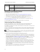

LED Name State Description
ACT
Off
No power, secondary control module is not synchronized with active
control module, or error condition.
Steady green
Active control module (serving network I/O).
Steady amber
Secondary control module. Cache is synchronized with active control
module.
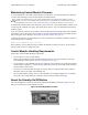
Identifying Control Module Failures
You can identify a failure in a control module by:
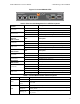
• LEDs on the control module itself. See Interpreting Control Module LEDs on page 16.
• Messages on the console, in the event log, or in the Group Manager GUI Alarms panel.
• Group Manager GUI and CLI output. The Member Controllers window or the member select
show controllers command output shows the control module status not installed.
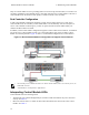
When viewed from the rear of the array, CM0 is on the top and CM1 is on the bottom. See Front-
Panel Features and Indicators on page 3.
If a control module fails, contact your PS Series support provider for a replacement.
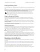
Understanding Failover Behavior
In a dual control module array, only one control module is active (processing network I/O and
performing storage functions) at one time. Each control module stores recently used data.
For redundancy, the cache on the secondary control module mirrors the data that is stored in the cache
on the active control module.
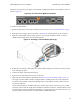
The active control module can use the network interfaces of the secondary control module for failover
if a cable is connected from the corresponding port on the secondary control module to a functioning
network switch.
The management ports on the control modules do not fail over if one control module fails. Therefore,
if you are using a dedicated management network, make sure the management ports on both control
modules are connected to the management network.
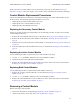
A PS Series array provides the following types of network failure protection:
• Vertical failover. In a dual control module array, a network port on the active control module can
fail over to the same network port on the other (secondary) control module if a network path fails.
For example, if Ethernet 0 on CM0 loses connectivity (switch 0 fails), Ethernet 0 on CM1 cache is
enabled and utilized. See Dual Controller Configuration on page 16 for details.
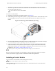
• Control module failover. In a dual control module array, if the active control module fails, the
secondary control module automatically takes over and becomes active.
If a cable is connected to a network port on the newly active control module, network I/O can
switch to its network interface. Depending on circumstances, network I/O might instead continue
through the previously active control module. (For example, the control module that becomes
active can use either its own local network interface, or the network interface on the previously
active control module.)
Control module failover occurs automatically, and if iSCSI initiators reconnect to the group IP
address, application I/O can continue without user intervention.
18
PS6210 Hardware Owner's Manual 3 Maintaining Control Modules