
Owners Manual

PS6210 Hardware Owner's Manual 3 Maintaining Control Modules
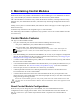
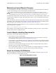
Facing the rear of the array, the upper control module is CM0 and the lower control module is CM1, as
shown in Figure 20.
Figure 20: Correct Control Module Orientation
To install a control module:
1. Attach an electrostatic wrist strap or similar protective device. See Protecting Hardware on page
1.
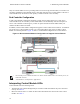
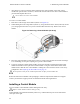
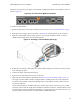
2. Push down on the orange release tab (callout 1 in Figure 21) and swing the lever out (callout 2).
3. Slide the control module into the chassis until it is even with the installed controller. The lever
should swing smoothly until it is in the locked position.
Figure 21: Installing a Control Module (4U Array)
4. Rotate the lever inward, which pushes the control module completely into the slot. The latch on the
lever will snap into place.
5. Connect all cables (network and serial port).
6. If the array was shut down, turn on power to the array.
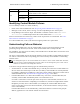
7. Make sure the control module is operational. See Interpreting Control Module LEDs on page 16.
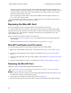
The Type 15 control module contains an integral battery assembly used in the cache-to-flash fea-
ture of the control module. If the Group Manager GUI or CLI indicates a battery failure, the bat-
tery must be replaced.
If two control modules are installed in the array, but only one is shown in the GUI (or CLI), make
sure that you have allowed enough time (minimum of 5 minutes) for the two control modules to boot
and synchronize. When synchronization completes, a message appears on the serial console (if con-
nected), and the ACT LED on the secondary module is illuminated amber.
23