Dell Product Name Dell PowerEdge R510 N Excellent balance of internal storage, redundancy, and value in a compact chassis.
This document is for informational purposes only. Dell reserves the right to make changes without further notice to any products herein. The content provided is as is and without express or implied warranties of any kind. Dell, the Dell logo, PowerEdge, and ReadyRails are trademarks of Dell, Inc. Citrix and XenServer are registered trademarks of Citrix Systems, Inc. and/or one or more of its subsidiaries, and may be registered in the United States Patent and Trademark Office and in other countries.
Contents 1 Overview........................................................................................................ 7 1.1 Product Description ..................................................................................... 7 1.2 Product Comparison ..................................................................................... 8 2 New Technologies ............................................................................................ 10 2.1 Detailed Information ......................
.11.4 5 6 7 8 Top Cover .......................................................................................... 33 4.12 USB Key .................................................................................................. 33 4.13 Battery ................................................................................................... 34 4.14 Field Replaceable Units (FRU) ........................................................................ 34 Power, Thermal, Acoustic .....................
10.2 Riser 2 Detail ............................................................................................ 53 10.2.1 PCI Device information .......................................................................... 54 10.2.2 Boot Order for Riser 2............................................................................ 54 10.2.3 PCI Card Dimensions ............................................................................. 54 11 Storage .......................................................
Table 25. Table 26. Table 27. Table 28. Table 29. Table 30. Table 31. Table 32. Table 33. Table 34. Table 35. Raid Configurations for the PowerEdge R510-8 .......................................................... 57 RAID Configuration for PowerEdge R510-12 .............................................................. 59 Microsoft Operating Systems Supported ................................................................... 64 Linux Operating Systems ......................................................
1 Overview 1.1 Product Description The Dell™ PowerEdge™ R510 is a 2-socket, 2U high-capacity, multi-purpose rack server offering an excellent balance of internal storage, redundancy, and value in a compact chassis. The Dell PowerEdge R510 was developed with a purposeful design, energy-optimized technology, the performance of the Intel® Xeon® processors and enterprise-class manageability.
1.1.5 Dell Services Dell Services can help reduce IT complexity, lower costs, and eliminate inefficiencies by making IT and business solutions work harder for you. The Dell Services team takes a holistic view of your needs and designs solutions for your environment and business objectives while leveraging proven delivery methods, local talent, and in-depth domain knowledge for the lowest TCO. 1.
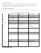
PowerEdge 2950 III (Predecessor) PowerEdge R710 (Current) PowerEdge R510 (New) Cooling Hot-swap, Redundant Hot-swap, Redundant R510-12 supports redundant fan Diagnostic LCD LCD LED for PowerEdge R510-4 and R510-12 LCD for PowerEdge R510-8 Systems management BMC+DRAC 5 iDRAC 6 Express Optional iDRAC6 Enterprise and vFlash BMC, IPMI 2.
2 New Technologies A number of new technologies have been incorporated into the PowerEdge R510 product, including: • • • • • • • 2.
Chipset 2.2.1 PCIe Generation 2 PCIe Gen2 provides the next generation of I/O bandwidth to the system. PCIe Gen2 doubles the signaling bit rate of each lane from 2.5 GT/s to 5 GT/s. 2.2.2 DDR3 Memory Technology Intel Xeon processor 5500 and 5600 series support new DDR3 memory technology, which replaces fully buffered DIMMs in the new Intel architecture. Native DDR3 memory capability improves memory access speed, lowers latency, and allows more memory capacity. 2.2.
3 System Overview PowerEdge R510 is a value 2-socket 2U server, with maximized storage capacity, high performance, simplified management, and an affordable price. Table 2.
PowerEdge R510–4 drives PowerEdge R510–8 drives PowerEdge R510-12 drives Dimension (HxWxD) 3.40 x 17.19 x 24.09 (in); 86.4 x 436.6 x 610.2 (mm) 3.42 x 17.53 x 26.17 (in); 86.7 x 445.2 x 664.6 (mm) Max Weight 16 Kg/35.2 lbs 22.5 Kg /49.5 lbs 29 Kg/63.8 lbs Empty Weight 13.6 Kg/29.92 lbs 13.5 Kg/29.7 lbs 15.85 Kg/34.87 lbs Bezel Metal (Optional) HDD Bays 4 x 3.5" Cabled HDD 8 x 3.5" Hot-swap HDD or 8 x 2.5" Hot-swap HDD 12 x 3.5" Hot-swap HDD + 2 x 2.5" Internal Cabled HDD or 12 x 2.
PowerEdge R510–4 drives PowerEdge R510–8 drives PowerEdge R510-12 drives HDD/SSD NA 2.5" (in hard drive carrier through conversion kit) 25GB SATA SSD 50GB SATA SSD 100GB SATA SSD 2.5" (in hard drive carrier through conversion kit) 25GB SATA SSD 3.1 50GB SATA SSD 3.
PowerEdge R510–4 drives PowerEdge R510–8 drives PowerEdge R510-12 drives NICs/Dual Port Intel PRO/1000 PT Dual Port Server Adapter Intel Gigabit ET Dual Port Server Adapter Broadcom NetXtreme II 5709 Dual Port Ethernet PCIe Card with TOE 3.
PowerEdge R510–4 drives PowerEdge R510–8 drives PowerEdge R510-12 drives RHEL 4.7 ES/AS x86(DIB) RHEL 4.7 ES/AS 64-bit(DIB) RHEL 4.7 for HPC x86-64 (DIB) RHEL 5.3 Standard/AP x86(DIB) RHEL 5.3 Standard/AP 64-bit (FI) RHEL 5.
4 Mechanical 4.1 Chassis Description PowerEdge R510 chassis is a 2U rack system. The chassis is not swappable. Supported configurations are detailed in Table 3. Supported Chassis Configurations Table 3. 4-HDD Configuration 8-HDD Configuration 5 x cabled 3.5” HDD bay Non-Redundant 480W PSU Quad pack diagnostic LED 12-HDD Configuration 8 x hot-swap 3.5” or 2.5” HDD bay 750W redundant PSU (n+0 or n+1 option) 11G diagnostic LCD (identical to the PowerEdge R710) 12 x hot-swap 3.5” or 2.
Figure 2.
4.3 Front Panel View and Features Figure 3. PowerEdge R510–4 HDD Configuration Figure 4.
Figure 5. PowerEdge R510–12 HDD Configuration 4.3.1 NMI Button The Non-Maskable Interrupt (NMI) button can be accessed through a pin hole with a thin object (e.g., the end of a paperclip). Pressing this button results in a Non-Maskable Interrupt to the CPU, which halts all CPU operations. 4.3.2 System ID Button There are 2 System ID buttons—one on the front panel of all servers and one on the back panel of rack-dense and rackable tower servers.
The Power LED has two states: Power LED is OFF: System is not operating, regardless of AC present. (Other AUX powered subsystems may be operational with AC power present.) • Power LED is ON (Green): System is operating. One or more of the non-standby (Vaux) power rails are active. All PowerEdge servers include a green colored LED on the motherboard to indicate the presence of standby power (Vaux). This LED is in a visible location for service personnel.
This hierarchy dictates that connections that are lower in the hierarchy be disabled anytime a higher level connection is disabled. 4.3.6 DVD/CD If present, the DVD/CD drive has an eject mechanism and a green activity LED. The eject mechanism is functional with or without power. 4.3.7 Hard Drive Activity LED The PowerEdge R510 systems have a single (common) green hard drive activity LED that lights when the system is accessing data on the drive. These systems do not have Status LEDs. 4.3.
4.4 Back Panel View and Features Figure 8. R510 with Non-Redundant Power Supply for PowerEdge R510-4 ONLY Figure 9. With Redundant Power Supply for PowerEdge R510-8 and 12 Figure 10. Non-redundant Power Supply Option on PowerEdge R510-8 and 12 Only redundant Power Supply Units (PSUs) have a LED indicator to show the power supply status.
Figure 11. Redundant PSU Status lights provide indications as follows: • • • • Not lit: AC power is not connected. Green: In standby mode, a green light indicates that a valid AC source is connected to the power supply and that the power supply is operational. When the system is on, a green light also indicates that the power supply is providing DC power to the system. Amber: Indicates a problem with the power supply.
4.6 Internal Chassis Views Battery Holder Figure 14. PowerEdge R510-4: Non-Redundant PSU and the Battery Holder for PERC Card Figure 15.
Figure 16. PowerEdge R510-12 Internal View (Redundant PSU with PDB and Additional Fan for PSU) Figure 17.
4.
4.8 Rail View Figure 18. R510 Sliding Rails without CMA Figure 19.
Figure 20. R510 Static Rails Figure 21. R510 Static Rails in Rack 4.9 Fans 4.9.1 Fan module PowerEdge R510-4 and PowerEdge R510-8 have the same fan module.
Figure 22. Fan Module for R510-4 and 8 PowerEdge R510-12 has redundant fans stacked in modules. Figure 23. Fan Module for R510-12 4.9.2 Fan Location and Installation PowerEdge R510-4 has four fan modules (it does not have the fan circled in red as shown in Figure 24). PowerEdge R510-8 has five fan modules. PowerEdge R510-12 has five redundant fan modules which contain 2 fans each for a total of 10 fans.
Figure 24. Fan Location 4.9.3 Fan Connector and Connector Locations Figure 25.
4.10 Cabling Table 8.
4.11.2 Hard Drive Security Hard drives are only accessible by unlocking and opening the bezel. 4.11.3 Intrusion Switch The intrusion switch is located inside the chassis under the top cover. The switch alarms if the top cover is opened while the power is on. 4.11.4 Top Cover The top cover latch has a coin lock. 4.
The PowerEdge R510-12 internal USB connectors are on the backplane as shown below. Figure 28. PowerEdge R510–12 USB Connector 4.13 Battery A replaceable lithium battery (CR2032) is mounted on the motherboard to provide backup power for the Real-Time Clock in the ICH10R and CMOS RAM on the Super I/O controller. 4.
5 Power, Thermal, Acoustic 5.1 Power Supplies The 4-HDD configuration includes a 480W power supply. The 8- and 12-HDD configurations have a hot-plug redundant 1100W power supply. A hot-plug redundant 750W option is available for the 8- and 12-HDD configurations. Power is soft-switched, allowing power cycling using a switch on the front of the system enclosure or using software control (through server management functions). The power system is compatible with industry standards, such as ACPI and Server 2000.
Pin 1 2 3 4 SIGNAL GND GND GND GND Pin 5 6 7 8 SIGNAL P12VA P12VA P12VB P12VB Figure 30. Connector (8 pins) 5.2 Thermal Optimized thermal management makes PowerEdge R510 cool and quiet. Benefiting from a smart cooling thermal control algorithm, the PowerEdge R510 can keep both high performance and good acoustics across a wide range of ambient temperatures (10 °C – 35 °C). In addition, the PowerEdge R510 provides cooling efficiency that saves energy.
Table 9. Environmental Specifications Operating Requirements Temperature Ranges (For Altitude ≤900 m or 2952.75 ft) 10 to 35 °C (50 to 95 °F) 1 Non-Operating Requirements -40 to 65 °C (-40 to 149 °F) Temperature Ranges (For Altitude > 900 m or 2952.75 ft) 10 to Note °C (50 to Note2 °F) Temperature Gradient Maximum per 60 Min.
5.5 Energy Star Compliance See the ENERGY STAR Compliance results on Dell.com. 5.6 Acoustics The acoustical design of the PowerEdge R510 reflects the following: • • • Adherence to Dell’s high sound quality standards. Sound quality is different from sound power level and sound pressure level in that it describes how humans respond to annoyances in sound, like whistles, hums, etc.
Table 10. Typical Configuration @ 23 ± 2 °C CPU HDD RAID 2 x Intel E5506/2.13GHz 2 x 146GB SAS (3.5”/ 7200 RPM) 1x PERC S300 Max. Configuration @ 23 ± 2 CPU 2 x Intel X5570/2.80GHz Acoustics of 4-HDD Chassis DIMM 4 x 2GB UDIMM °C HDD RAID 4 x 600GB SAS (3.5”/ 15k RPM) 1x PERC 6/i (H700) Table 11. Typical Configuration @ 23 ± 2 DIMM 8 x 4GB RDIMM °C HDD RAID DIMM 2 x Intel E5506/2.13GHz 4 x 500 GB Hotplug SATA (3.
Definitions Standby: AC Power is connected to Power Supply Units but system is not turned on. Idle: Reference ISO7779 (1999) definition 3.1.7; system is running in its OS but no other specific activity. Stressed Processor: An operating mode per ISO7779 (1999) definition 3.1.6. The software MemBW4 is activated to stress the processors. LwA – UL: The upper limit sound power level (LwA) calculated per Section 4.4.2 of ISO 9296 (1988) and measured in accordance to ISO 7779 (1999).
6 Processors R510 can operate in either single-processor or dual-processor mode. However, since the memory controller is embedded in the processor, when only one processor is installed in the system, it supports 4 DIMMs, with minimum memory of 1GB and maximum memory of 64GB (based on the 16GB module). When two processors are installed in the system, it supports 8 DIMMs, min. 2GB and max 128GB (based on the 16GB module). Table 13.
7 Memory 7.1 Overview Please carefully review this entire section Features of the PowerEdge R510 memory include: • • • • • • 3 channels per processor Support for registered ECC DDR3 DIMMs or Unbuffered ECC DDDR3 DIMMs. DDR3 speeds of 800/1066/1333 supported (Max memory clock speed support is pending on the processors used. Refer to table in Section 8C.
8 Chipset 8.1 Overview Introduction of the new Intel Xeon processor 5600 series includes a stepping revision of the Intel 5520 and 5500 chipset, which is required to enable the full 5600 series feature set. Dell servers shipped with the new chipset revision have the symbol II in the System Revision Field visible through OpenManage™ Server Administrator (OMSA) and the iDRAC GUI. They are physically marked with a 12 x 6mm rectangular label containing the symbol II.
8.2.
9 BIOS 9.1 Overview A flash resides on the SPI bus for BIOS and configuration storage. A 32 Mbit device is used for this function. This permits the BIOS to be upgraded in the field via a bootable device rather than by physically removing an EEPROM. The System BIOS, Video BIOS, server management, and PCI configuration are housed in this flash. The following table clarifies what is and is not supported by the PowerEdge R510 BIOS code. Table 14.
AC recovery staggering Power-Up Power Inventory (PSU, CPU, and DIMM mismatch checking) Support for Multiple power profiles Static Maximum Performance Mode OS Control(DBS) Active Power Controller Custom 9.2 ACPI BIOS is compliant with ACPI version 2.0a. ACPI features consist of two types: configuration features and power management features. The features supported on this system are described below. 9.2.1 Configuration • PCI Routing Table (_PRT).
Table 15. Summary of Power Management Features Feature Type Enable/Status/ Ctrl bit location Description ACPI Mode Switch Fixed ICH-10 The OS uses the SCI_EN bit in ICH to switch from legacy mode to ACPI mode. Sleep States Fixed ICH-10 Supported states: S0 (Working), S4-OS (Hibernation in Windows OS), and S5 (Soft-off). S1 (also called standby or suspend) and S3 are not supported. Power Button Fixed ICH-10 In ACPI mode, OS has control of the power button.
Table 16.
9.3 UEFI and ACPI For PowerEdge R510 systems, the UEFI layer does not participate in generation of the ACPI (Advanced Configuration and Power Interface) table. The ACPI table is generated by the BIOS and UEFI exposes the ACPI table as an EFI configuration table entry. See the UEFI 2.1 specification for the details on EFI configuration table and the ACPI_TABLE_GUID. 9.
Table 18. Intel 5600 Chipset P-State Projections and Turbo Mode Frequency QDF# Frequency (GHz) P-state Turbo Mode Freq (Ghz) Stepping E5503 Q2HH 2.00 Pmin+3 n/a D0 E5506 Q1GL 2.13 Pmin+4 n/a D0 E5507 Q2HG 2.26 Pmin+5 n/a D0 L5520 Q1GN Pmin+5 4C/3C: 2.40 2C/1C: 2.53 D0 E5530 Q1GK Pmin+6 4C/3C: 2.53 2C/1C: 2.66 D0 E5620 Q4EK Pmin+6 4C/3C: 2.53 2C/1C: 2.66 B1 L5609 Q4F8 Pmin+2 n/a B1 E5630 Q4EU Pmin+7 4C/3C: 2.66 2C/1C: 2.80 B1 L5640 Q4EQ Pmin+5 6C/5C: 2.
Table 19. UEFI Summary UEFI IS • • • • • Compliant with UEFI spécification 2.1 A layer on top of the existing legacy BIOS Independent of processor and chipset technology. Running in 64-bit long mode Supportive of GUID Partition Table (GPT) formatted disks PowerEdge R510 Technical Guide UEFI IS NOT • • • • • • A PIWG (DXE, PEI) implementation A complete rewrite of the system firmware Developed as a server UEFI implementation or desktop and notebook implementations.
10 I/O Slots 10.1 Overview The PowerEdge R510 system provides two configurations for I/O slots: • • 10.1.1 Riser 1 (default offering): Three PCIe slots (x4, x4, x8 bandwidth; all w/ x8 slots) + One internal storage slot (x4 bandwidth w/ x8 slot for SAS or PERC integrated cards only) Riser 2 (for GPGPU ONLY): One PCIe slot (x16 bandwidth and slot) + One internal storage slot (x4 bandwidth w/ x8 slot for SAS or PERC integrated cards only) Riser 1 Detail Figure 31. Riser 1 Table 20.
10.1.2 • • • • • PCI Device Information IOH port 1, 2 (PCI Express Gen2 x4) – Broadcom BCM5716 Gigabit LOM IOH port 3 (PCI Express Gen2 x4) – Slot 4 IOH port 7/8 (PCI Express Gen2 x8) – Slot 3 IOH port 9 (PCI Express Gen2 x4) – Slot 2 IOH port 10 (PCI Express Gen2 x4) – Slot 1 10.1.
Riser 2 Slot Information Table 22.
11 Storage 11.1 Overview There are two types of chassis for R510. • • 4 Hard Drive Chassis: x cabled 3.5” HDD (cabled HDD carrier, identical to R410 cabled HDD carrier), support one slim optical disk drive (ODD) 8 Hard Drive Chassis: 8 x hot-swap 3.5” or 2.5” HDD (in hard drive carrier), support one slim ODD 11.2 Drives Refer to Table 2 for more information on available drives. Figure 33. 2.
11.3 RAID Configurations Table 24. Raid Configurations for the PowerEdge R510-4 PowerEdge R510-4 Factory Configuration No Mixed HDD (3.
Table 25. Raid Configurations for the PowerEdge R510-8 PowerEdge R510-8 Factory Configuration No Mixed HDD (Must be all 2.5" or 3.
R510-8 Mixed HDD (SAS + SATA) Factory Configuration Mixed SAS + SATA (Must be all 3.5" HDDs) (ex.
Table 26. RAID Configuration for PowerEdge R510-12 No Mixed HDD (Must be all 2.5" or 3.
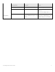
53 ASSR1/R1-X RAID1+RAID1 (PERC H200, PERC H700) 2+2 2+2 54 ASSR1/R5-X RAID1 + RAID5 (PERC H700) 2+3 2+ 10 55 ASSR5/R10-X RAID5 + RAID10 (PERC H700) 4+4 4+8 R510-12 Mixed HDD (SSD + SAS) Factory Configuration Mixed SSD + SAS (Must be all 2.5" HDDs) (ex.
68 ASSR50/+iR1 RAID50 (PERC H700) 6 12 69 ASSR60/+iR1 RAID60 (PERC H700) 8 12 70 ASSR1/R1/+iR 1 RAID1+RAID1 (PERC H200, PERC H700) 2+2 2+2 71 ASSR1/R5/+iR 1 RAID1 + RAID5 (PERC H700) 2+3 2+ 10 72 ASSR5/R10/+i R1 RAID5 + RAID10 (PERC H700) 4+4 4+8 R510-12 Mixed HDD ( + + ) Factory Configuration Mixed SAS + SATA (Must be all 3.5" HDDs) (ex.
11.4 Optical Drives R510 supports a SATA interface slim DVD-ROM or slim DVD+/-RW. Slim ODD option is available on 4-HDD and 8-HDD configuration chassis only. R510-12 does not support internal ODD; external USB ODD options are available. 11.5 Tape Drives R510 does not support an internal backup device. Only external backup devices are supported. See Table 2 for more information.
12 Video The Matrox G200eW w/ 8MB memory integrated in WPCM450 (BMC controller) provides: • • • • • • • 1280x1024@85Hz for KVM and 1600x1200@60Hz for video out 640x480 (60/72/75/85 Hz; 8/16/32-bit color) 800x600 (60/72/75/85 Hz; 8/16/32-bit color) 1024x768 (60/72/75/85 Hz; 8/16/32-bit color) 1152x864 (75 Hz; 8/16/32-bit color) 1280x1024 (60/75/85 Hz; 8/16-bit color) 1280x1024 (60 Hz, 32-bit color) (note 32 bit color is only supported at 60 Hz for this resolution) PowerEdge R510 Technical Guide 63
13 Operating Systems For the most up-to-date information, see the Operating System Support Matrix for Dell PowerEdge Systems on Dell.com. The following tables provide information on operating systems supported on the PowerEdge R510. Table 27.
Web Standard Windows Server 2008 R2 (Windows 7 includes SP2 bits) x64 (only) Enterprise WHQL FI Datacenter HPC Server 2008 Table 28. Operating Systems Red Hat Enterprise Linux 4.7 Red Hat Enterprise Linux 4.
14 Virtualization Table 29. Supported Virtualization Operating Systems Operating Systems Factory Install (FI) Logo/Cert VMware ESX 4.0 DIB Yes VMware ESXi 4.0 (embedded version) Download version (NFI, No DIB) Yes VMware ESXi 4.0 (Hypervisor with USB Key) FI Yes VMware ESX 3.5 Update 4 DIB Yes VMware ESXi 3.5 Update 4 (embedded version) Download version (NFI, No DIB) Yes VMware ESXi 3.5 Update 4 (USB Key) FI Yes Citrix XenServer Enterprise 5.
15 Systems Management 15.1 Overview Dell delivers open, flexible, and integrated solutions that help you reduce the complexity of managing disparate IT assets by building comprehensive IT management solutions. Combining Dell PowerEdge Servers with a wide selection of Dell-developed management solutions gives you choice and flexibility, so you can simplify and save in environments of any size.
Remote Access Controller) is responsible for acting as an interface between the host system and its management software and the periphery devices. These periphery devices consist of the PSUs, the storage backplane, integrated SAS HBA or PERC 6/I, and control panel with display. The optional upgrade to iDRAC6 provides features for managing the server remotely or in data center lightsout environments. Advanced iDRAC features require the installation of the optional iDRAC6 Enterprise card. 15.
Secure operation of remote access functions including authentication, authorization, and encryption Power control and management with the ability to limit server power consumption and remotely control server power states • Advanced troubleshooting capabilities For more information on iDRAC6 Express features see table below. • • 15.6 iDRAC6 Enterprise The optional iDRAC6 Enterprise card provides access to advanced iDRAC6 features.
Feature BMC iDRAC6 Express iDRAC6 Enterprise vFlash Media Remote Management and Remediation Remote Firmware Update Server power control Serial-over-LAN (with proxy) Serial-over-LAN (no proxy) Power capping Last crash screen capture Boot capture Serial-over-LAN Virtual media Virtual console Virtual console sharing Virtual flash Monitoring Sensor Monitoring and Alerting Real-time P
16 Peripherals 16.1 USB peripherals Optional External USB DVD-ROM 16.2 External Storage Refer to Table 2 for information on external storage.
Appendix A. R510 Volatility Tables Table 32.
Control Panel Internal USB Y J_USBKEY (connector ) J_USB3, J_USB4 2 Varies by part number User selectable License key hard set ROM or user choice Up To 2 Maximum supported = 2MB per PSU.
Table 33.
Can user programs or operating system write data to it during normal operation? Purpose? No Backplane firmware (HDD status, etc.
How is data input to this memory? Planar System BIOS SPI Flash Loading flash memory requires a vendor-provided firmware file and loader program which is executed by booting up the system from a floppy or OS-based executable containing the firmware file and the loader. System loaded with arbitrary data in firmware memory will not operate.
How is data input to this memory? Storage Controller Processor Loading flash memory requires a vendor-provided firmware file and loader program which is executed by booting the system from a floppy or OS-based executable (DRMK, USC, OS DUPs utility support) containing the firmware file and the loader. Backplane loaded with bad firmware will not provide backplane and HDD status.
SAS 6/iR Integrated Controller Configuration Data FRU Integrated Mirroring NVSRAM Loading flash memory requires a vendor-provided firmware file and loader program which is executed by booting the system from a floppy or OS-based executable (DUPs, Unified Server Configurator) containing the firmware file and the loader. Storage adapters loaded with bad firmware will not provide storage controller behavior. Factory only. Not customer updatable.
How is this memory write protected? How is the memory cleared? writes controlled by iDRAC embedded OS EPPID is not clearable iDRAC embedded OS control of the write protection. Not possible with any utilities or applications and iDRAC does not function as expected if corrupted/removed. Lifecycle log is clearable only in a factory environment.
How is this memory write protected? How is the memory cleared? overwrite this EEPROM. IBUTTON Key EEPROM SHA1 encryption included. Storage Controller use only. N/A - not in system clearable CPLD Factory programmable only N/A - not in system clearable Controller Configuration Data Write control access by Storage Controller firmware N/A - not in system clearable FRU Protected in that no iDRAC embedded firmware writes to this device.