
Administrator Guide


Priority-Based Flow Control
In a data center network, priority-based ow control (PFC) manages large bursts of one trac type in multiprotocol links so that it
does not aect other trac types and no frames are lost due to congestion.
When PFC detects congestion on a queue for a specied priority, it sends a pause frame for the 802.1p priority trac to the
transmitting device. In this way, PFC ensures that PFC-enabled priority trac is not dropped by the switch.
PFC enhances the existing 802.3x pause and 802.1p priority capabilities to enable ow control based on 802.1p priorities (classes of
service). Instead of stopping all trac on a link (as performed by the traditional Ethernet pause mechanism), PFC pauses trac on a
link according to the 802.1p priority set on a trac type. You can create lossless ows for storage and server trac while allowing for
loss in case of LAN trac congestion on the same physical interface.
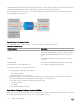
The following illustration shows how PFC handles trac congestion by pausing the transmission of incoming trac with dot1p
priority 3.
Figure 27. Priority-Based Flow Control
In the system, PFC is implemented as follows:
• PFC is supported on specied 802.1p priority trac (dot1p 0 to 7) and is congured per interface. However, only two lossless
queues are supported on an interface: one for Fibre Channel over Ethernet (FCoE) converged trac and one for Internet Small
Computer System Interface (iSCSI) storage trac. Congure the same lossless queues on all ports.
• PFC delay constraints place an upper limit on the transmit time of a queue after receiving a message to pause a specied priority.
• By default, PFC is enabled on an interface with no dot1p priorities congured. You can congure the PFC priorities if the switch
negotiates with a remote peer using DCBX.
• During DCBX negotiation with a remote peer:
– If the negotiation succeeds and the port is in DCBX Willing mode to receive a peer conguration, PFC parameters from the
peer are used to congured PFC priorities on the port. If you enable the link-level ow control mechanism on the interface,
DCBX negotiation with a peer is not performed.
– If the negotiation fails and PFC is enabled on the port, any user-congured PFC input policies are applied. If no PFC input
policy has been previously applied, the PFC default setting is used (no priorities congured). If you do not enable PFC on an
interface, you can enable the 802.3x link-level pause function. By default, the link-level pause is disabled.
• PFC supports buering to receive data that continues to arrive on an interface while the remote system reacts to the PFC
operation.
• PFC uses the DCB MIB IEEE802.1azd2.5 and the PFC MIB IEEE802.1bb-d2.2.
Enhanced Transmission Selection
Enhanced transmission selection (ETS) supports optimized bandwidth allocation between trac types in multiprotocol (Ethernet,
FCoE, SCSI) links.
ETS allows you to divide trac according to its 802.1p priority into dierent priority groups (trac classes) and congure bandwidth
allocation and queue scheduling for each group to ensure that each trac type is correctly prioritized and receives its required
bandwidth. For example, you can prioritize low-latency storage or server cluster trac in a trac class to receive more bandwidth
and restrict best-eort LAN trac assigned to a dierent trac class.
Although you can congure strict-priority queue scheduling for a priority group, ETS introduces exibility that allows the bandwidth
allocated to each priority group to be dynamically managed according to the amount of LAN, storage, and server trac in a ow.
Data Center Bridging (DCB)
215