
Administrator Guide


58
Virtual Link Trunking (VLT)
Virtual link trunking (VLT) is supported on the MXL switch platform.
Overview
VLT allows physical links between two chassis to appear as a single virtual link to the network core.
VLT reduces the role of spanning tree protocols (STPs) by allowing link aggregation group (LAG) terminations on two separate
distribution or core switches, and by supporting a loop-free topology. (To prevent the initial loop that may occur prior to VLT being
established, use a spanning tree protocol. After VLT is established, you may use rapid spanning tree protocol (RSTP) to prevent loops
from forming with new links that are incorrectly connected and outside the VLT domain.)
VLT peer devices have independent management planes. A chassis interconnect trunk between the VLT chassis maintains
synchronization of L2/L3 control planes across the two VLT peers. The chassis interconnect trunk uses 10GE or 40GE user ports on
the chassis.
VLT provides Layer 2 multipathing, creating redundancy through increased bandwidth, enabling multiple parallel paths between
nodes and load-balancing trac where alternative paths exist.
A separate backup link maintains heartbeat messages across an out-of-band management network. The backup link ensures that
node failure conditions are correctly detected and are not confused with failures of the chassis interconnect trunk. VLT ensures that
local trac on a chassis does not traverse the chassis interconnect trunk and takes the shortest path to the destination via directly
attached links.
Virtual link trunking oers the following benets:
• Allows a single device to use a LAG across two upstream devices.
• Eliminates STP-blocked ports.
• Provides a loop-free topology.
• Uses all available uplink bandwidth.
• Provides fast convergence if either the link or a device fails.
• Optimized forwarding with virtual router redundancy protocol (VRRP).
• Provides link-level resiliency.
• Assures high availability.
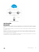
As shown in the following example, VLT presents a single logical Layer 2 domain from the perspective of attached devices that have
a virtual link trunk terminating on separate chassis in the VLT domain. However, the two VLT chassis are independent Layer2/Layer3
(L2/L3) switches for devices in the upstream network. L2/L3 control plane protocols and system management features function
normally in VLT mode. Features such as VRRP and internet group management protocol (IGMP) snooping require state information
coordinating between the two VLT chassis. IGMP and VLT congurations must be identical on both sides of the trunk to ensure the
same behavior on both sides.
826
Virtual Link Trunking (VLT)